Rare-earth-free joint motors: feasibility study
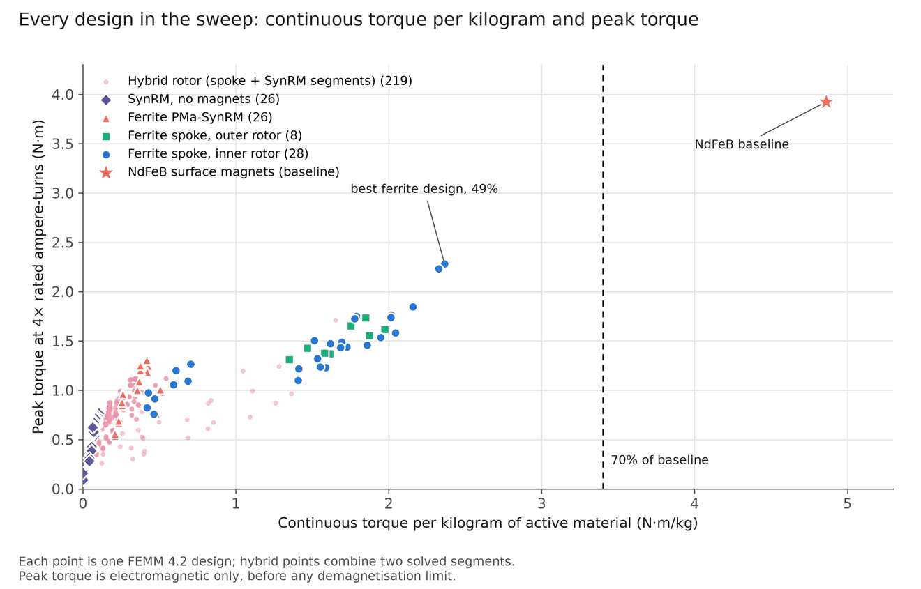
This feasibility study asks whether a rare-earth-free joint motor can reach 70% of the NdFeB baseline's continuous torque per active mass. None of the rare-earth-free designs meets that target. The best ferrite spoke rotor reaches 49% in 2D and 43% after the Elmer 3D end-leakage check. All results are simulated; no motor has been built.
The radial comparison holds the active envelope at 91 mm diameter, an 8 mm stack and 36 stator slots on a 48 V bus. Every design gets the same 17.8 W copper loss, set by the NdFeB baseline at an assumed 1.0 N·m continuous torque. The 70% target was chosen before the sweep.
I also checked axial-flux layouts and sized complete actuators for MABEL's arm and torso joints. The best axial ferrite design reaches 32% of the radial baseline, and axial NdFeB reaches 95%. In the main 64:1 actuator case, ferrite fails the mass criterion at all four joints. The sections below separate the fixed-envelope motor comparison, coupled actuator sizing and final per-joint 3D checks.
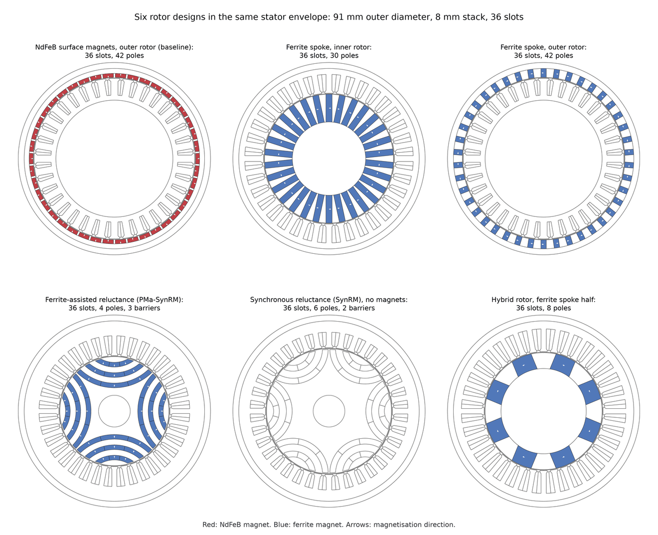
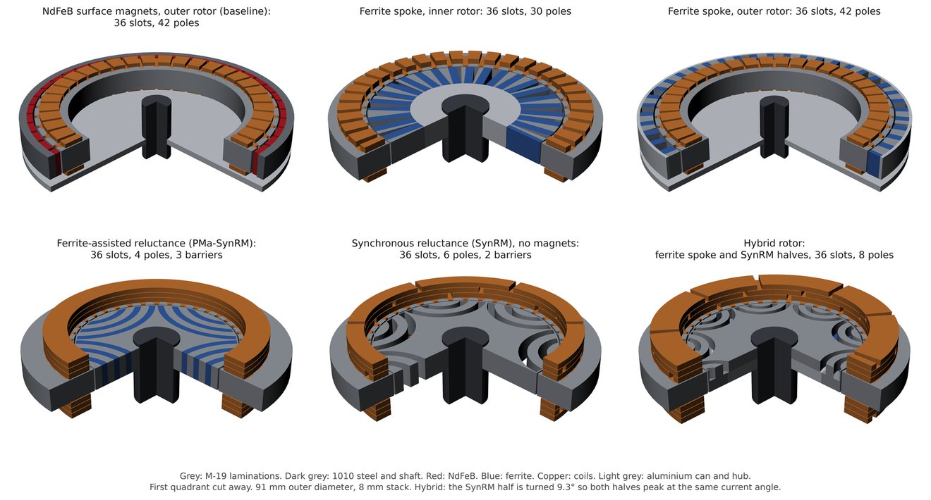
Results across all designs
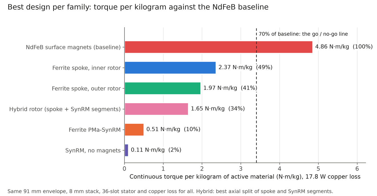
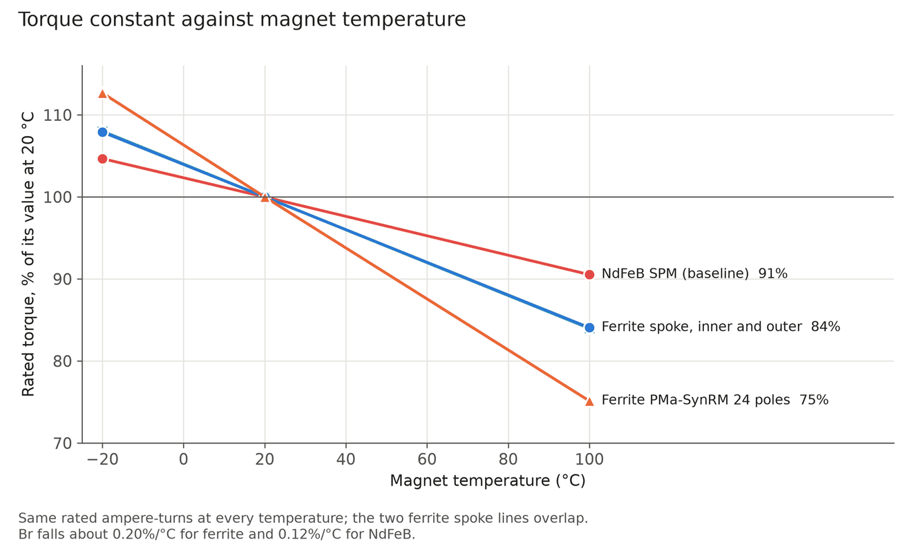
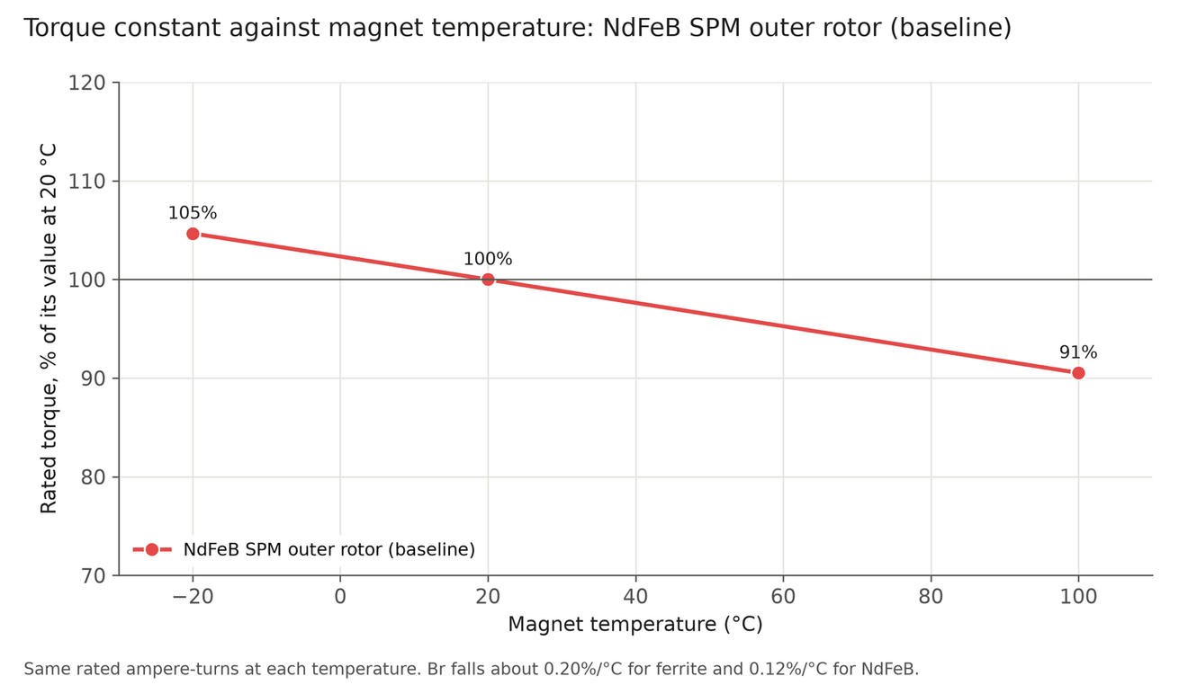
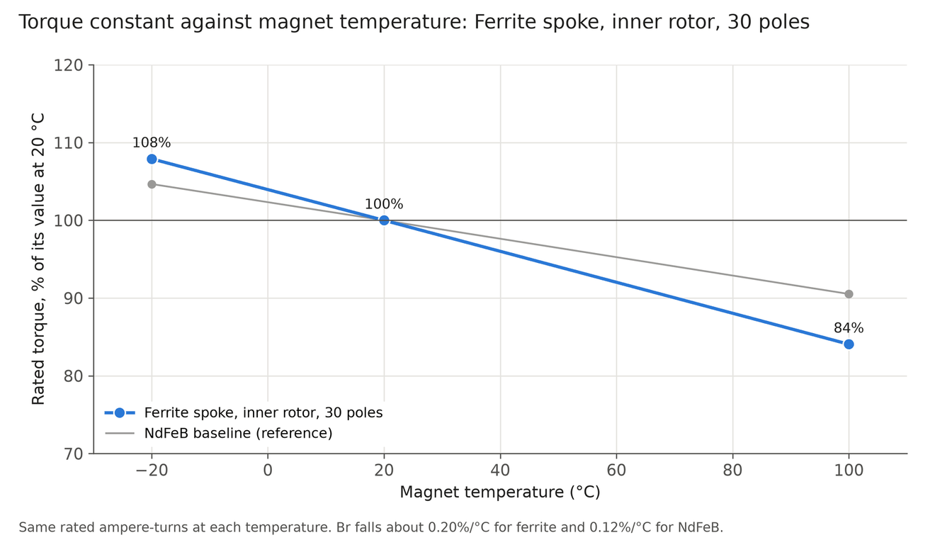
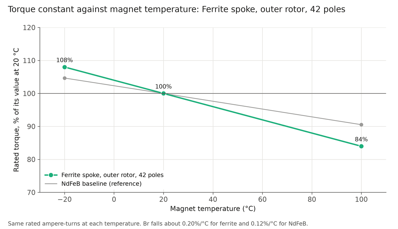
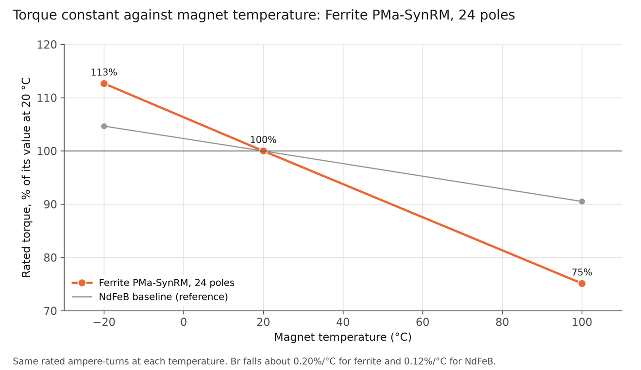
88 designs were swept, plus 219 hybrid pairings. The table gives the best design in each family at the same 17.8 W copper loss, with magnets at 20 °C. The verdict holds from −20 °C to 100 °C: the best spoke reaches 50% of the baseline when cold and 45% when hot.
| Family | Continuous torque | Torque per active mass | vs NdFeB | Peak at 4× current |
|---|---|---|---|---|
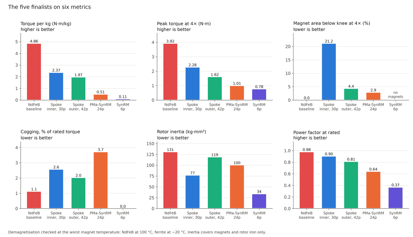
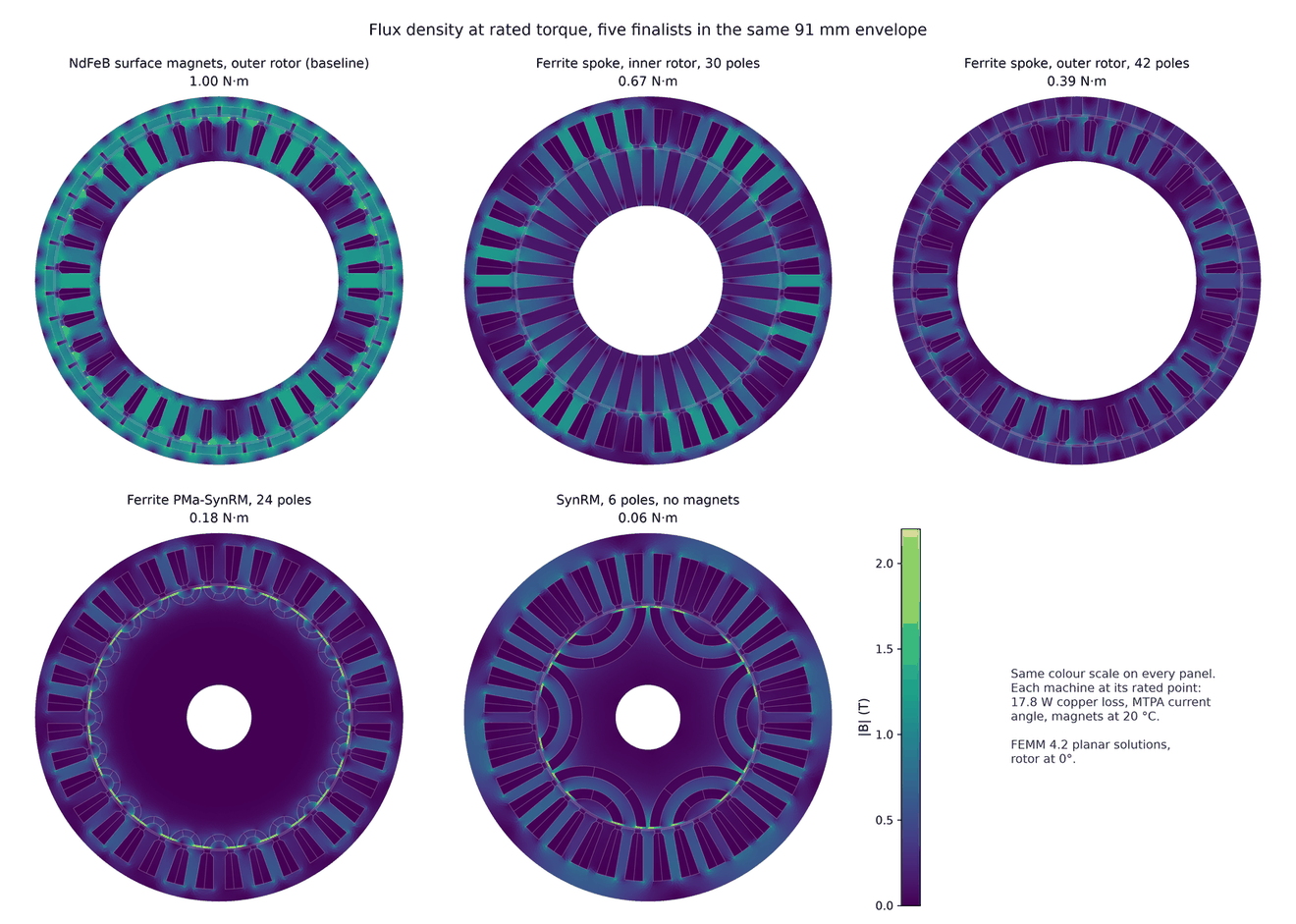
| NdFeB surface magnet (baseline) | 1.00 N·m | 4.86 N·m/kg | 100% | 3.92 N·m |
| Ferrite spoke, inner rotor | 0.67 N·m | 2.37 N·m/kg | 49% | 2.28 N·m |
| Ferrite spoke, outer rotor | 0.39 N·m | 1.97 N·m/kg | 41% | 1.62 N·m |
| Hybrid (ferrite spoke + reluctance) | 0.49 N·m | 1.65 N·m/kg | 34% | 1.71 N·m |
| Ferrite-assisted reluctance | 0.18 N·m | 0.51 N·m/kg | 10% | 1.01 N·m |
| Reluctance, no magnets | 0.06 N·m | 0.11 N·m/kg | 2% | 0.78 N·m |
NdFeB surface-magnet outer rotor (baseline)
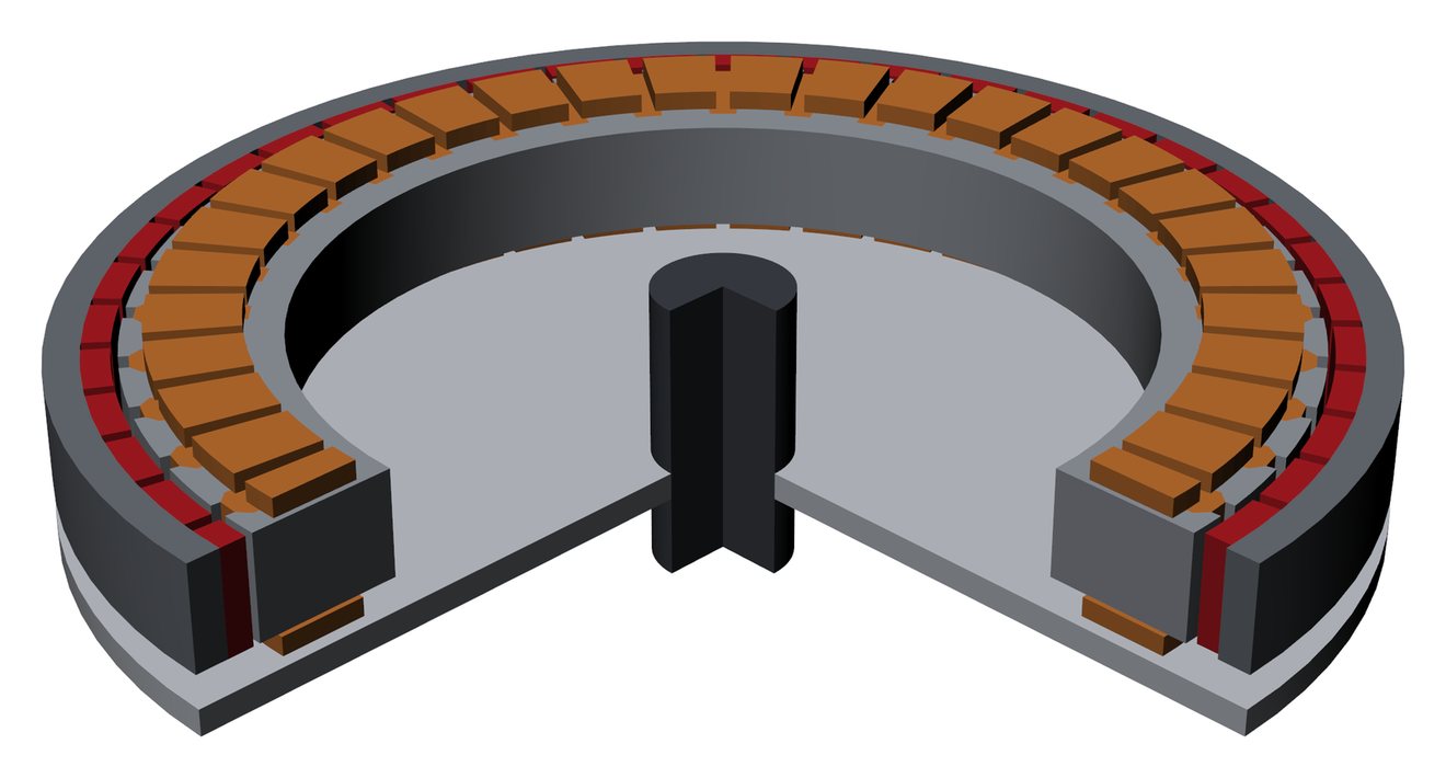
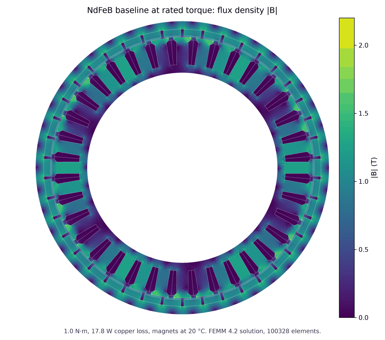
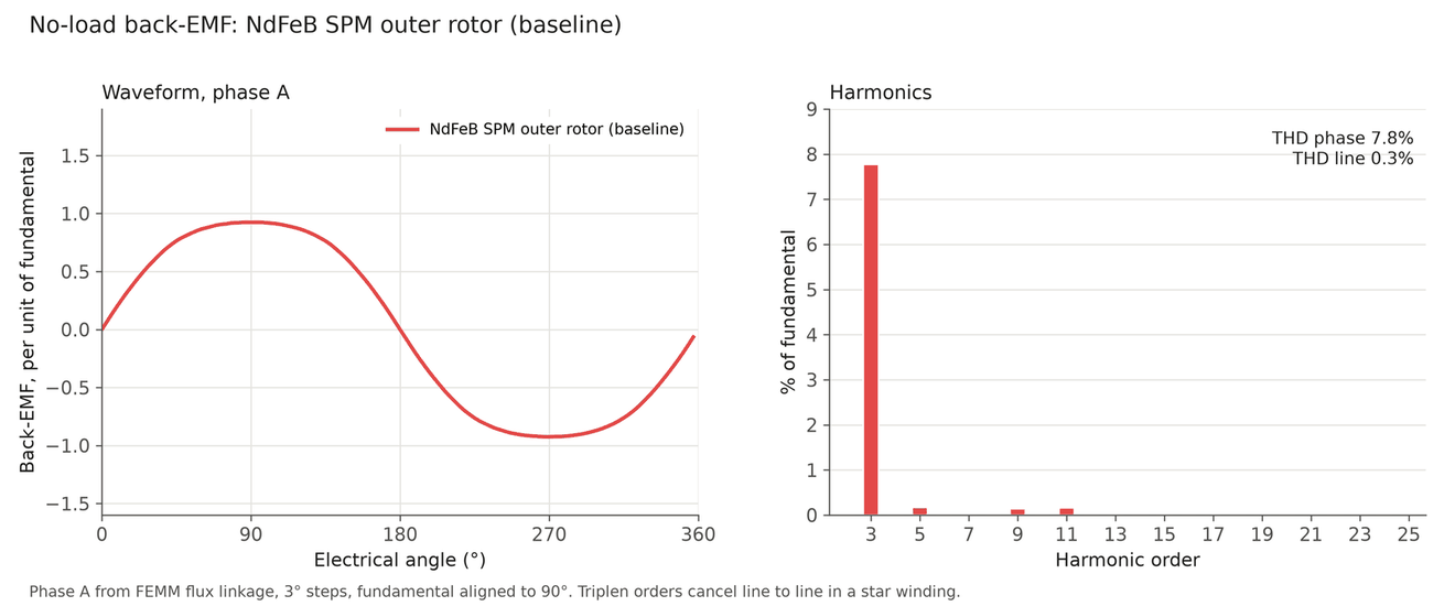
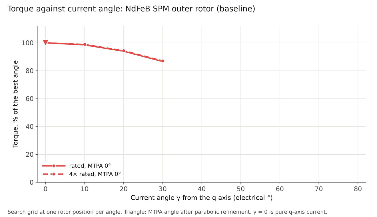
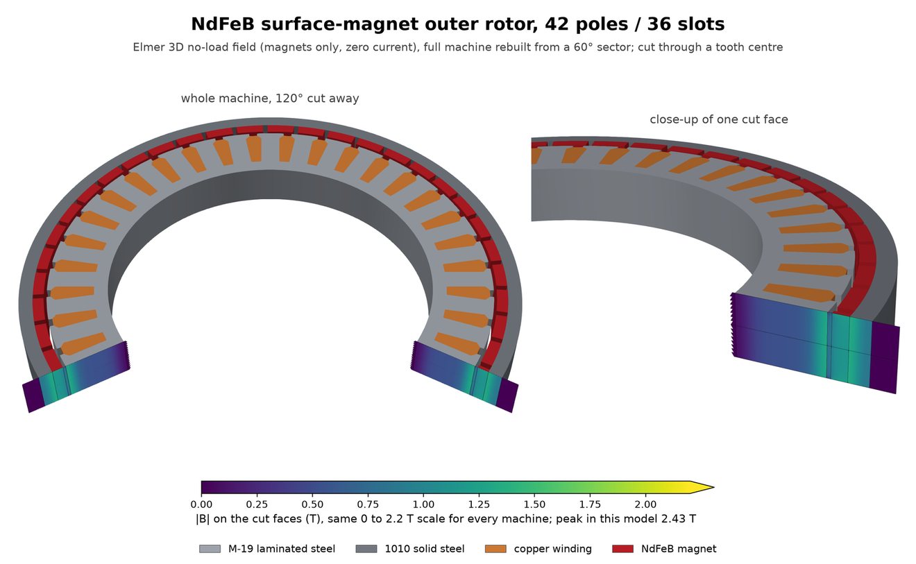
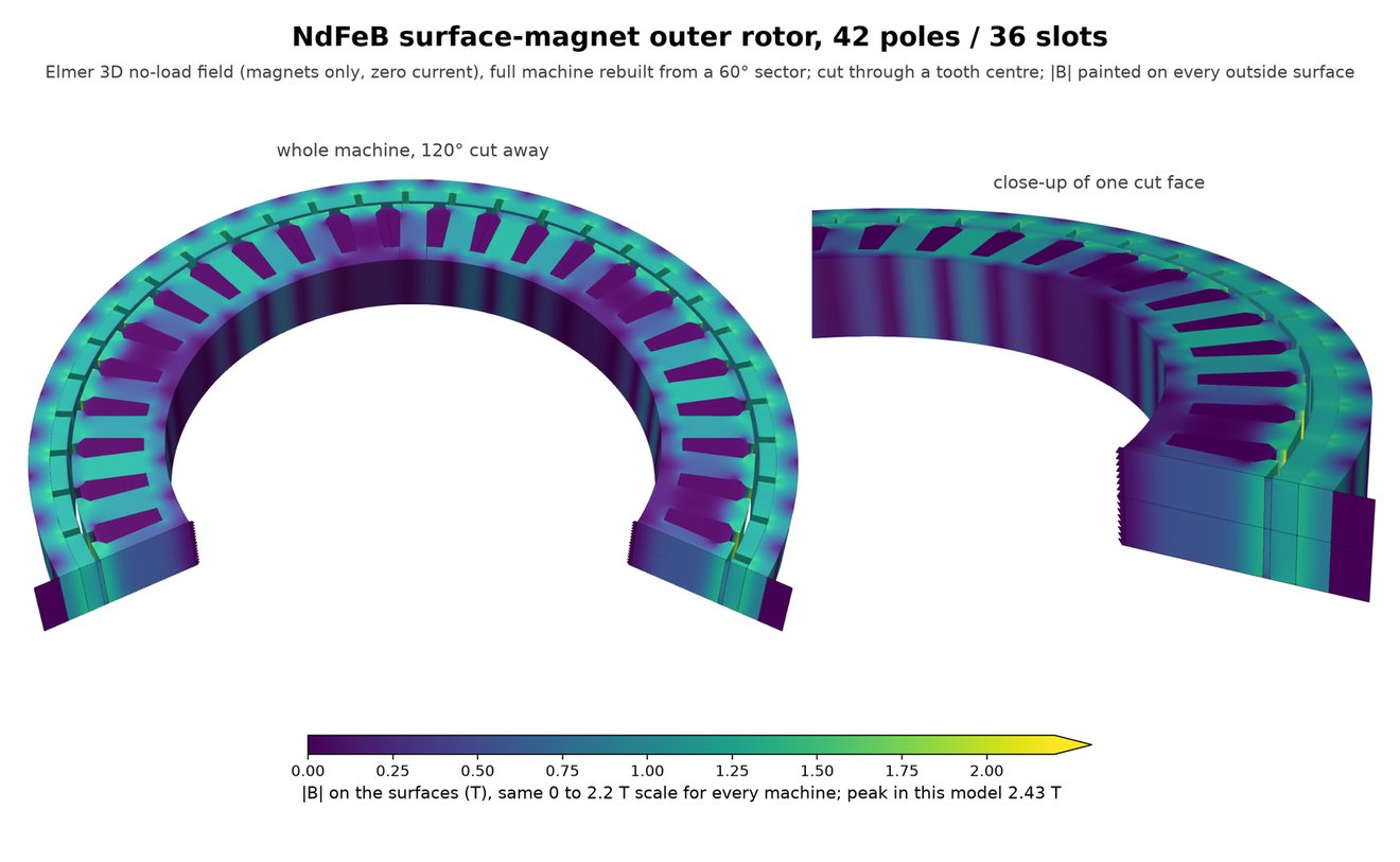
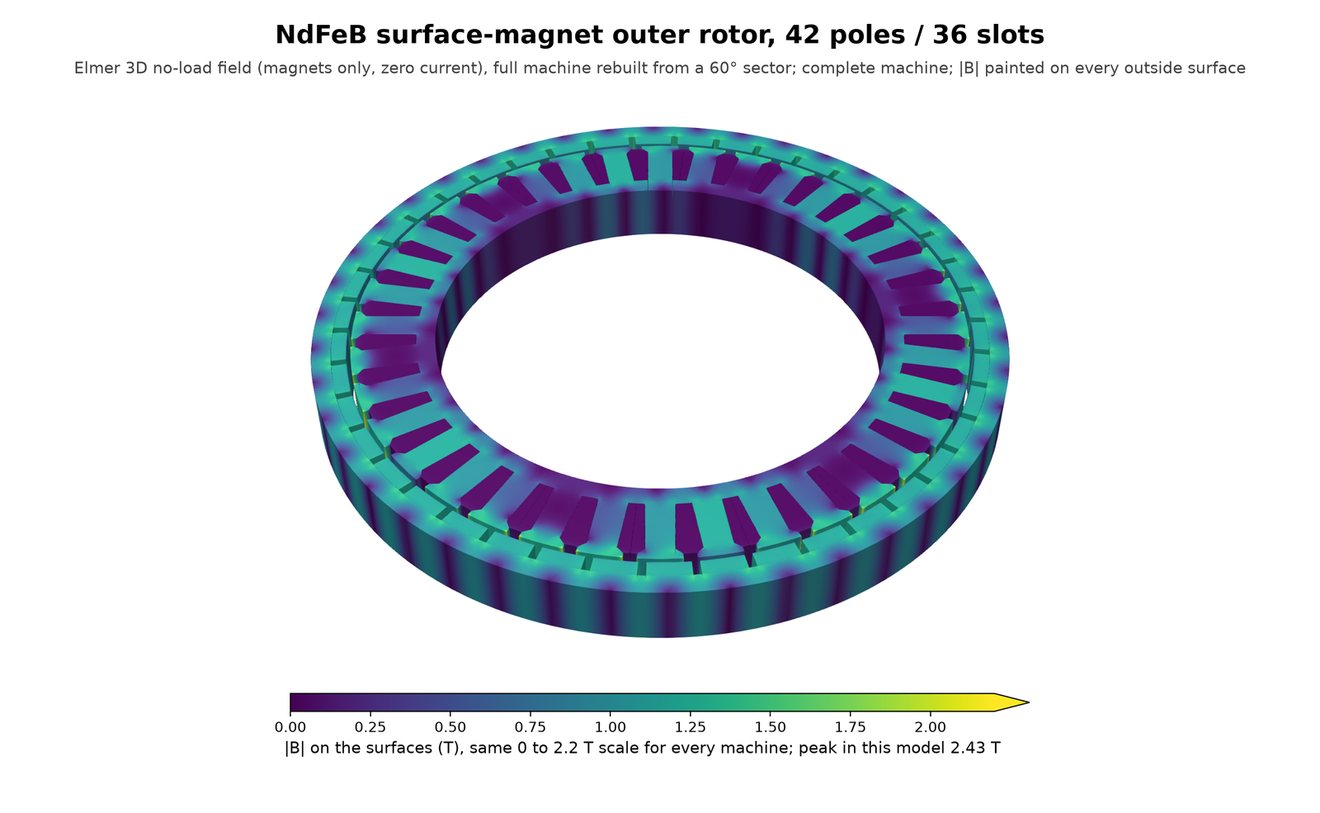
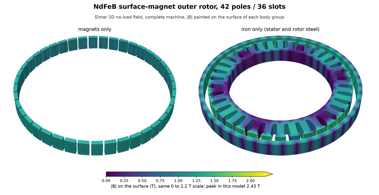
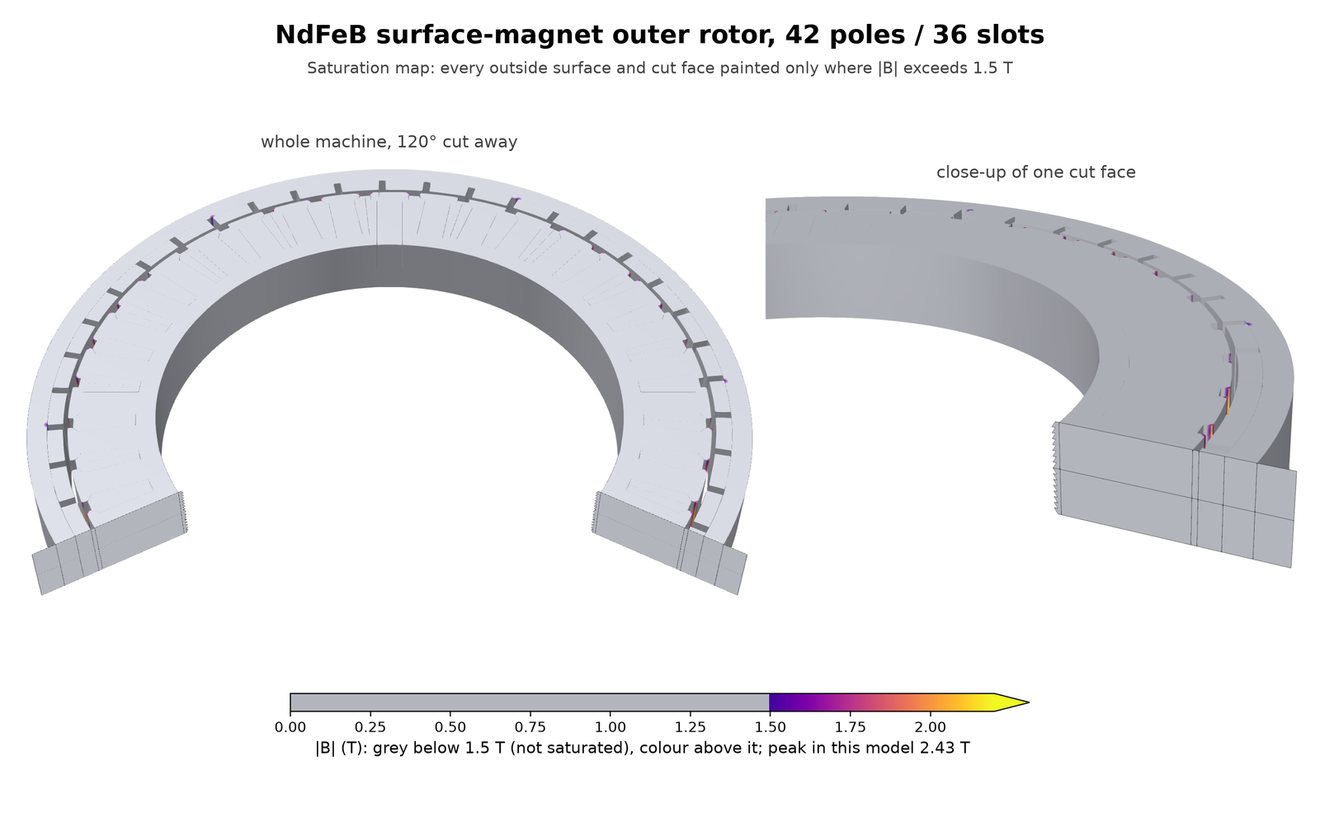
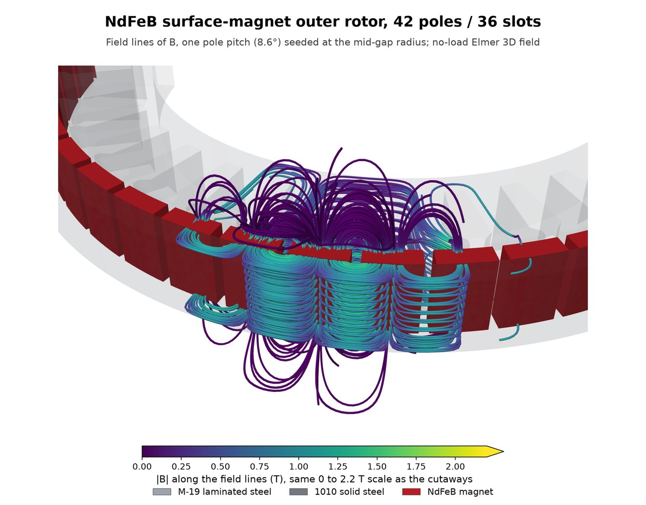
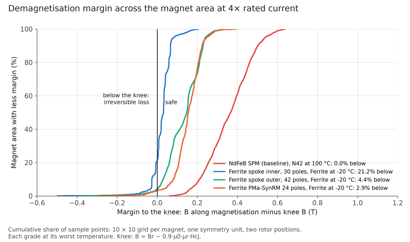
The baseline is a 42-pole outer rotor with 2 mm N42 arc magnets over a 36-slot tooth-coil stator, the usual layout for this class of joint motor. It makes 1.0 N·m at 17.8 W, with 26.9 g of magnet and 4.86 N·m/kg of active mass. At 4× current and 100 °C it keeps a 0.06 T margin above the demagnetisation knee.
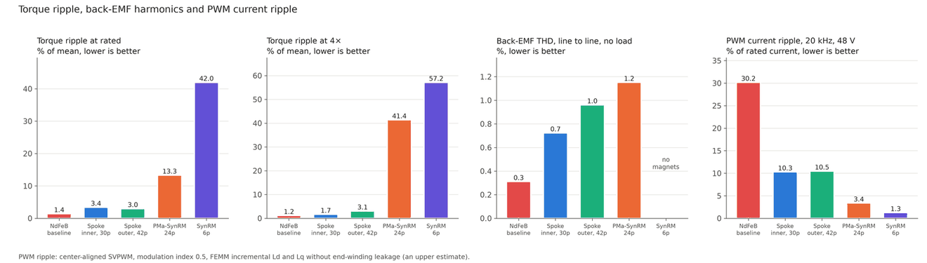
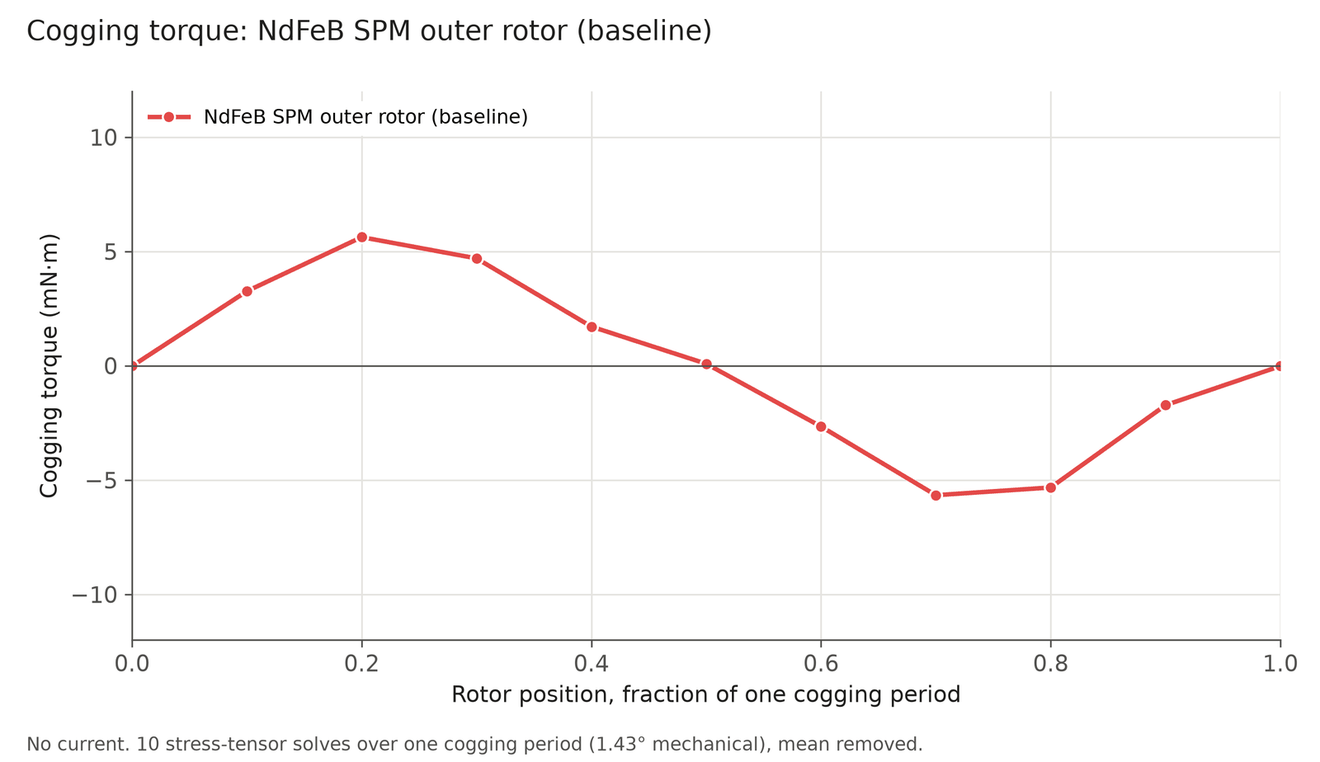
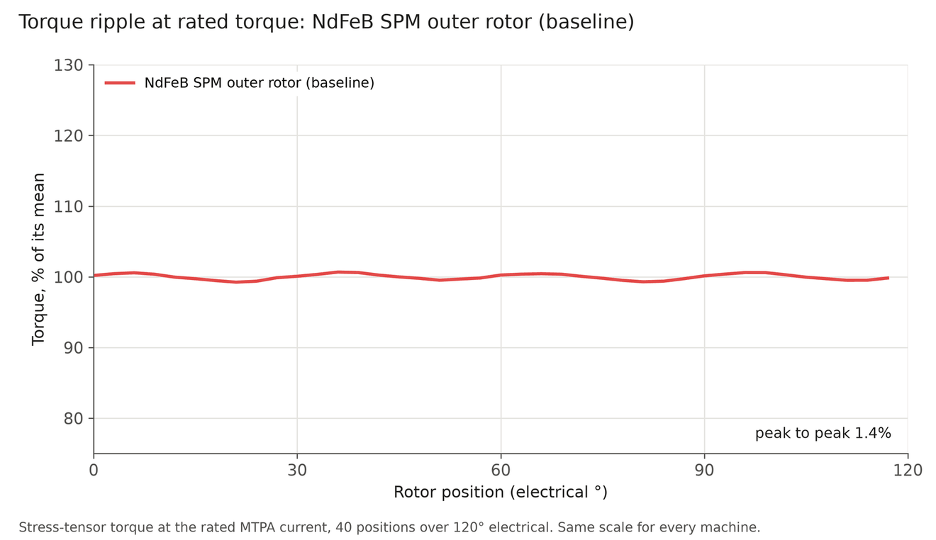
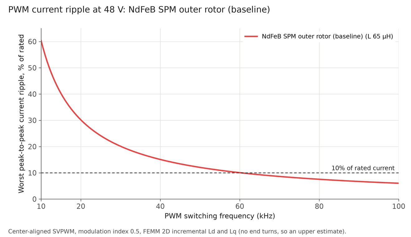
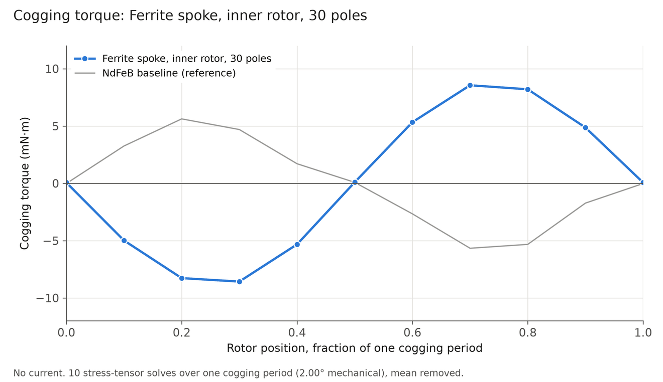
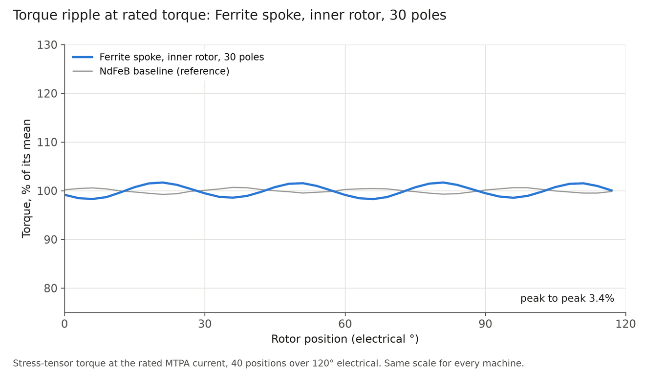
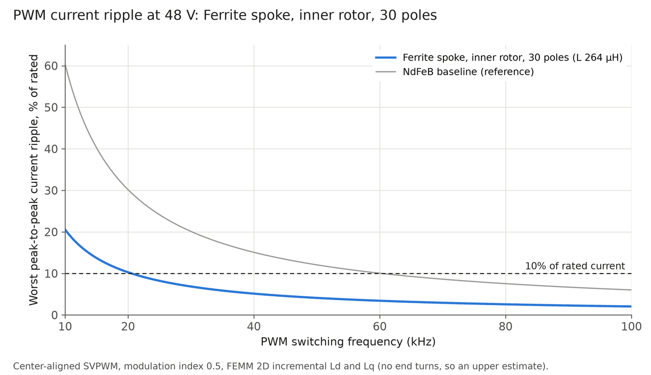
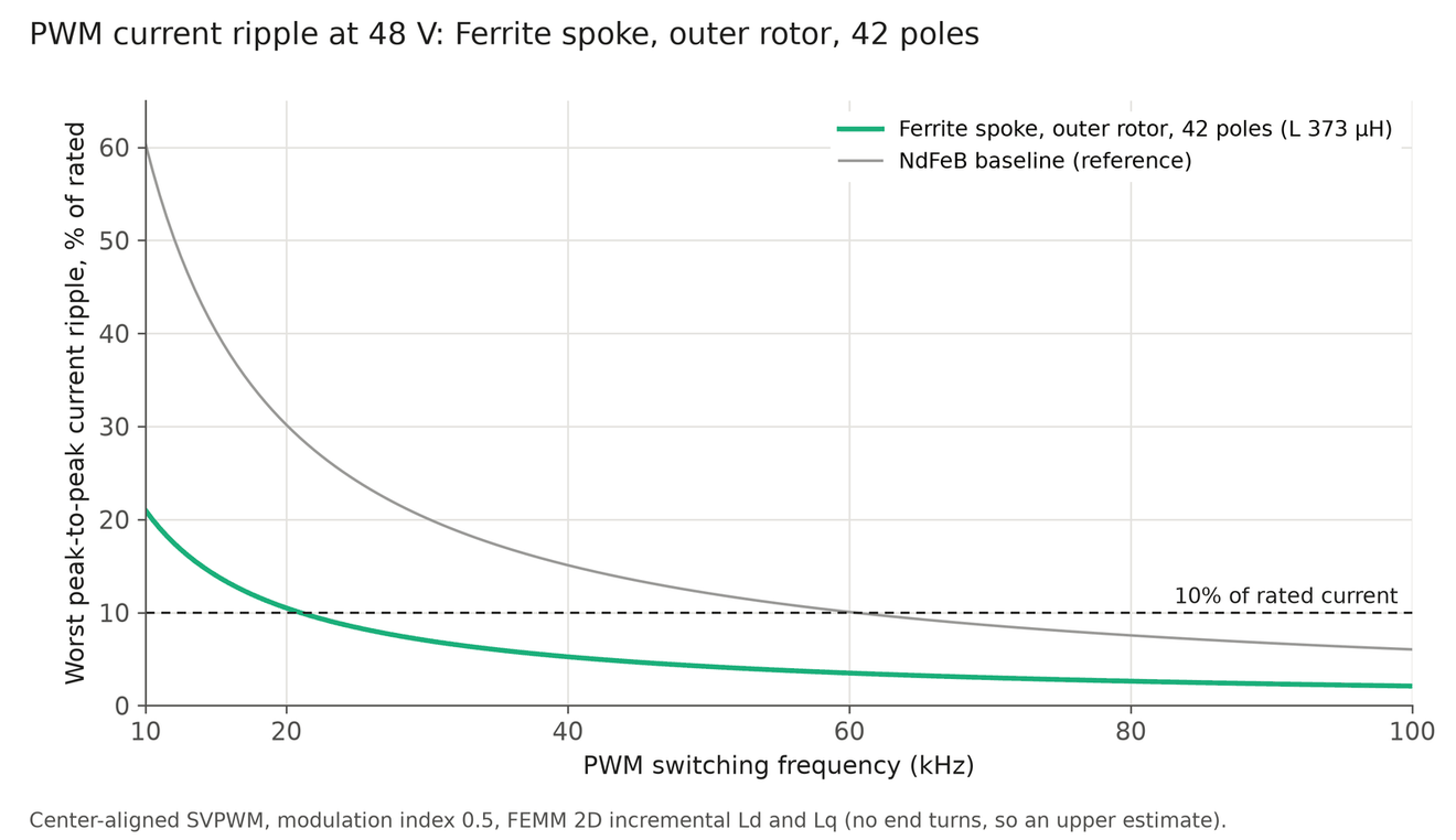
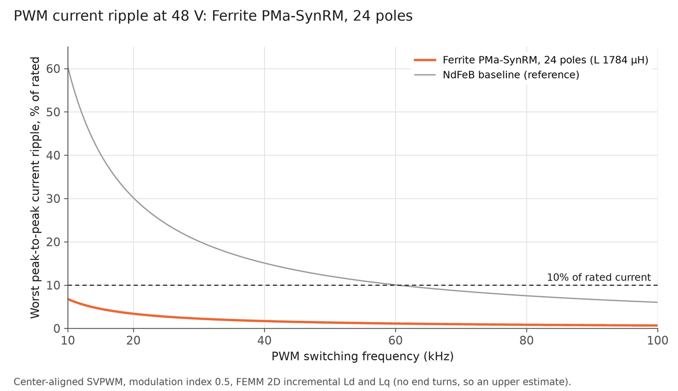
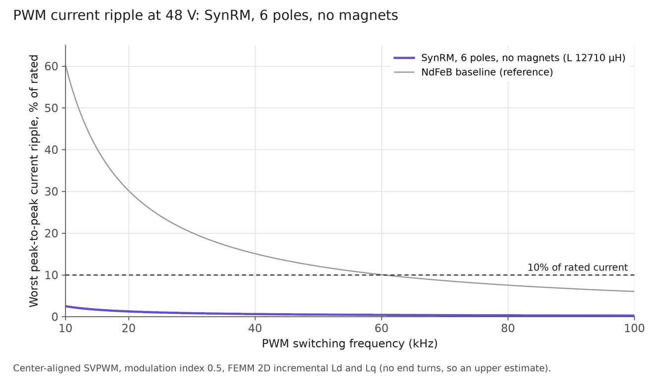
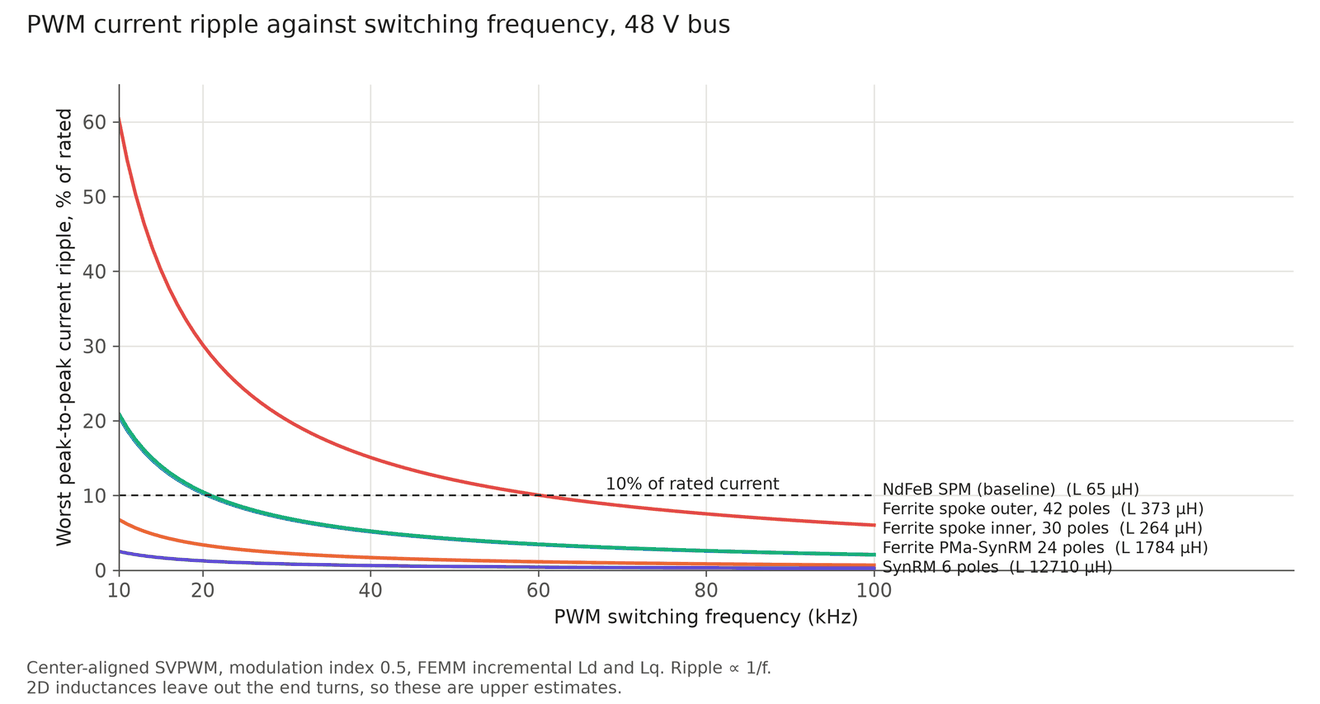
It is the smoothest machine here: 1.4% torque ripple and 1.1% cogging. Its weak point is for the drive, not the motor. With only 8 turns per coil its inductance is about 65 µH, so PWM current ripple at 20 kHz is about 30% of rated current. About 60 kHz brings that under 10%.
Ferrite spoke rotors
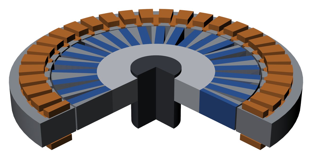
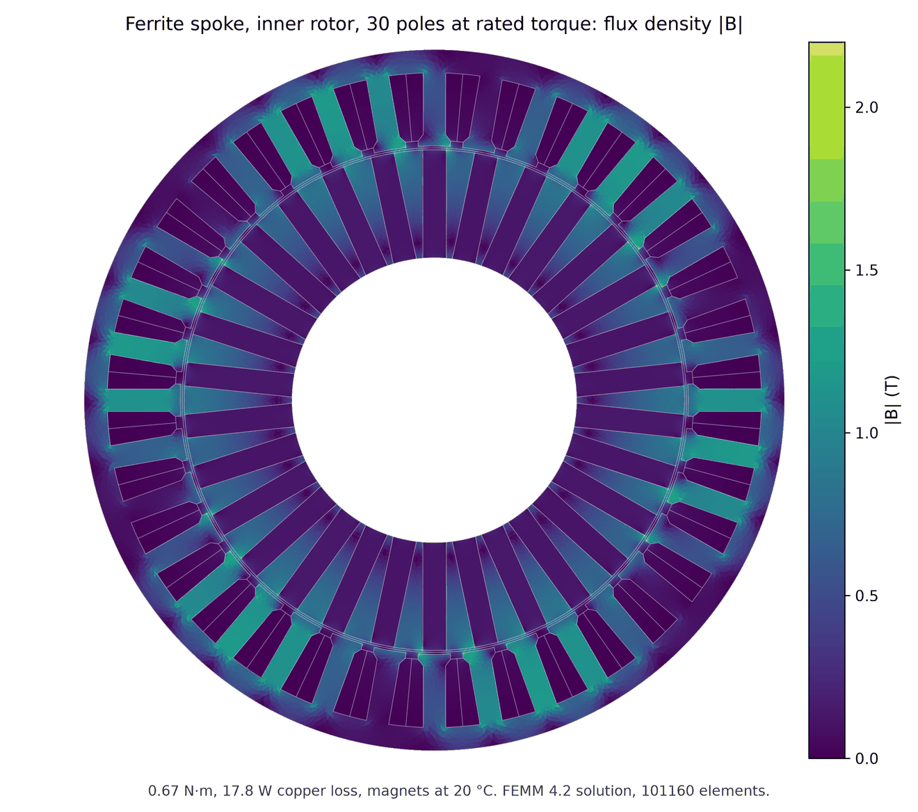
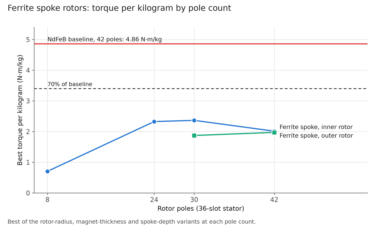
A spoke rotor stands ferrite magnets on edge between iron pole pieces, so the flux of two magnet faces adds into each pole. This is the strongest way to use ferrite, whose remanence is 0.40 T against 1.30 T for NdFeB. I swept 36 spoke designs, inner and outer rotor, from 8 to 42 poles. 24 to 30 poles works best: 8 poles collapses, and at 42 poles the narrow spokes leak too much flux.
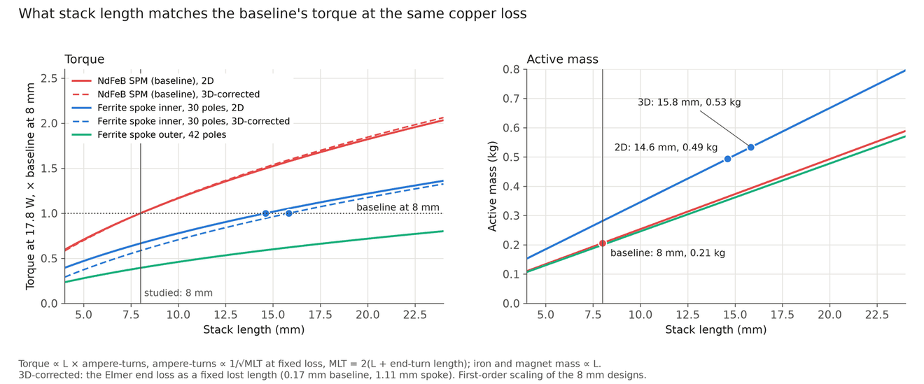
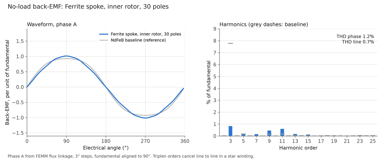
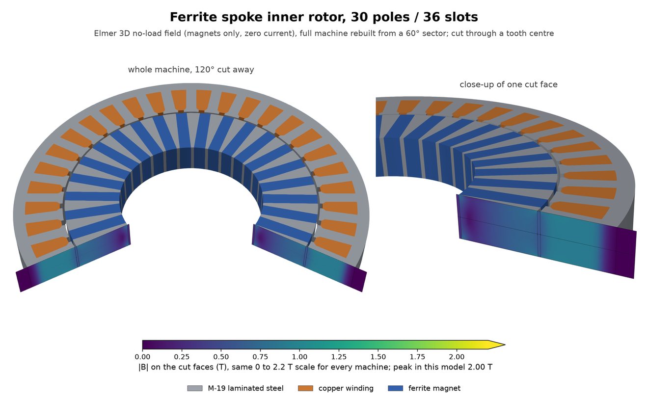
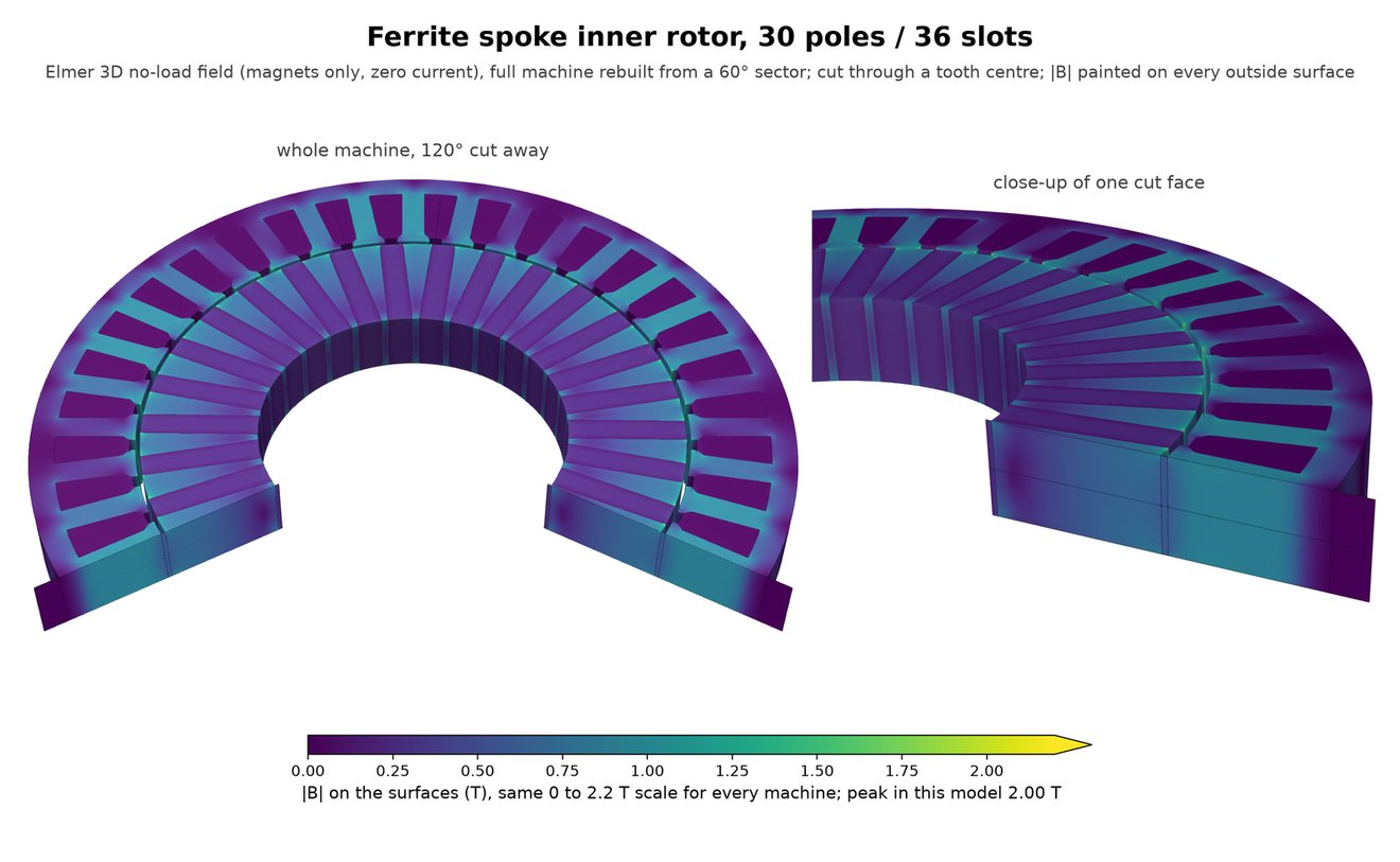
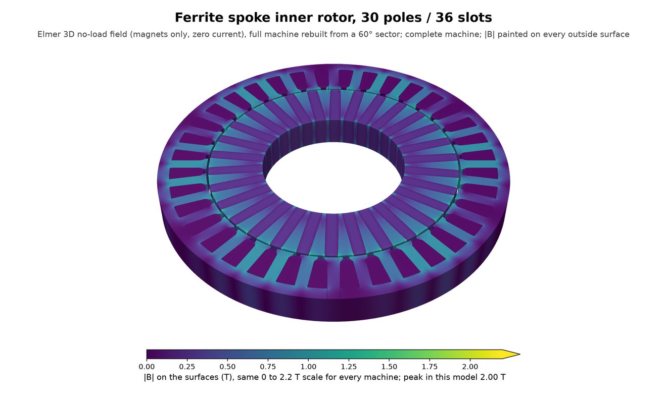
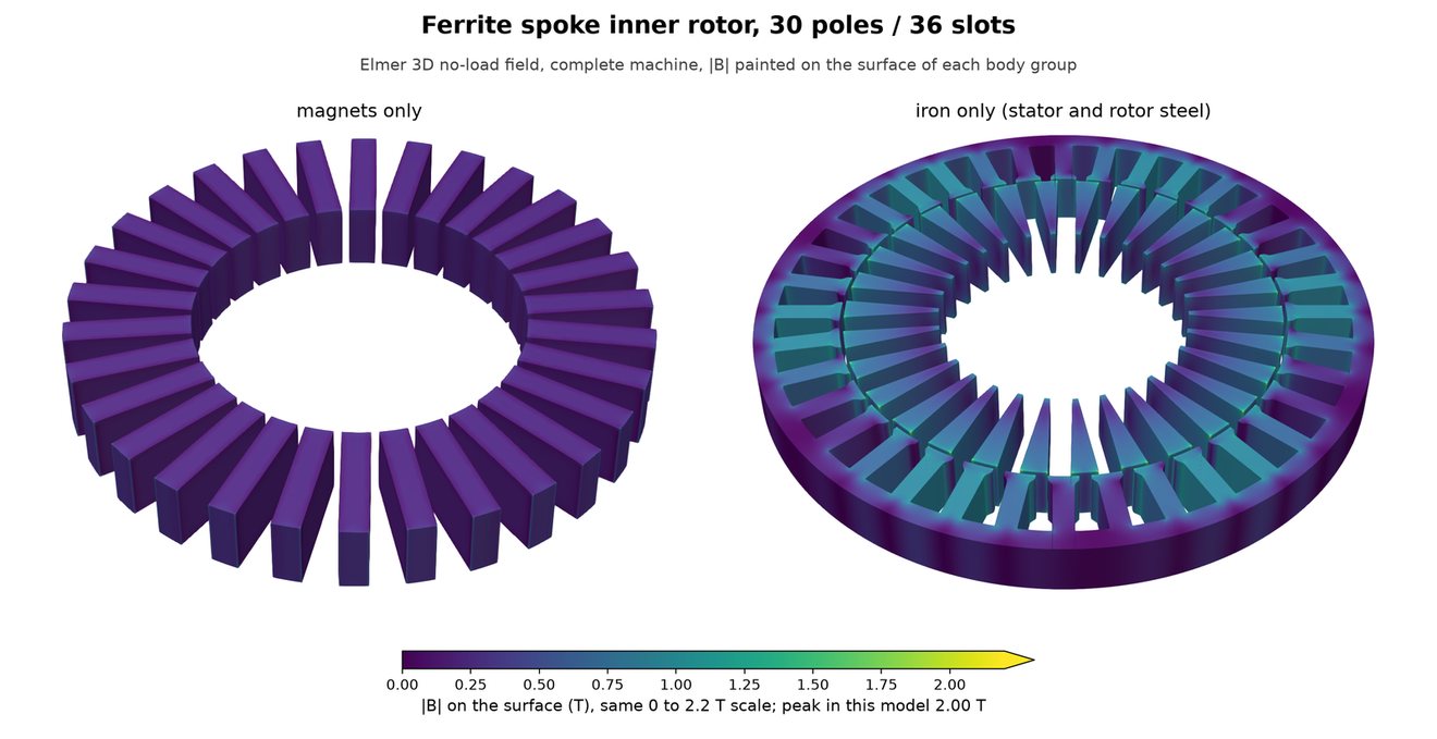
The best design is a 30-pole inner rotor with 14 mm deep spokes. It makes 0.67 N·m and 2.37 N·m/kg, 49% of the baseline in 2D and 43% after the 3D end-leakage correction. It also has the lowest rotor inertia here, 77 against 131 kg·mm². Matching the baseline's torque would need a stack of about 15.8 mm instead of 8 mm and 2.6 times the active mass.
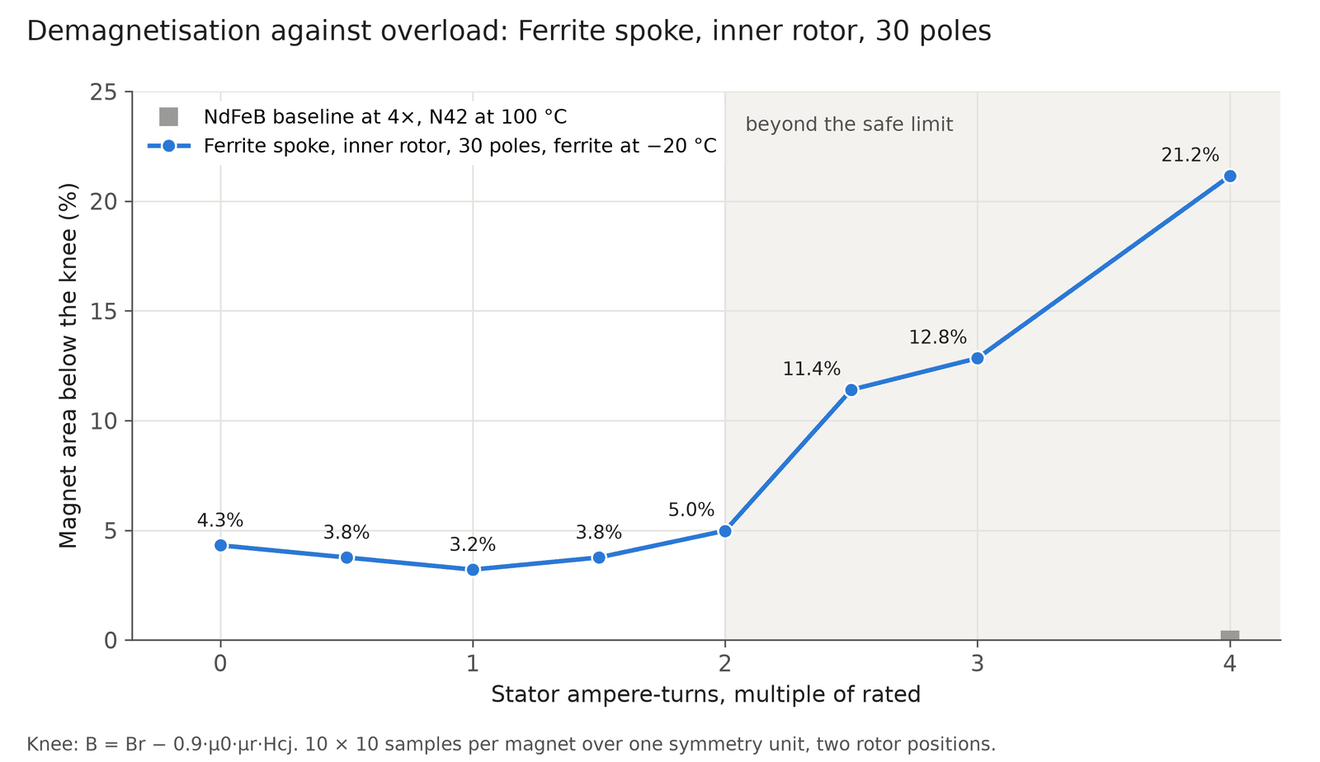
Its real limit is demagnetisation. Ferrite is weakest cold. At −20 °C about 4% of the magnet area sits below the knee even with no current, at the spoke corners, and current-driven damage starts spreading between 2× and 2.5× rated. So its usable peak is about 2× rated, not 4×.
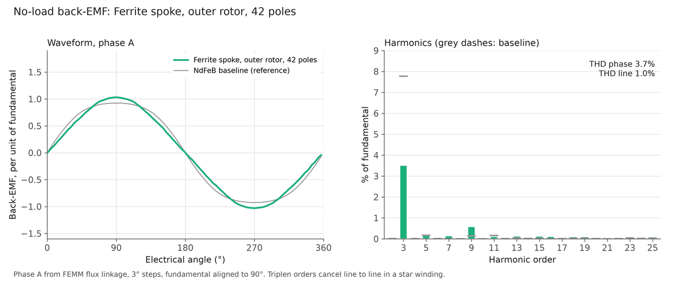
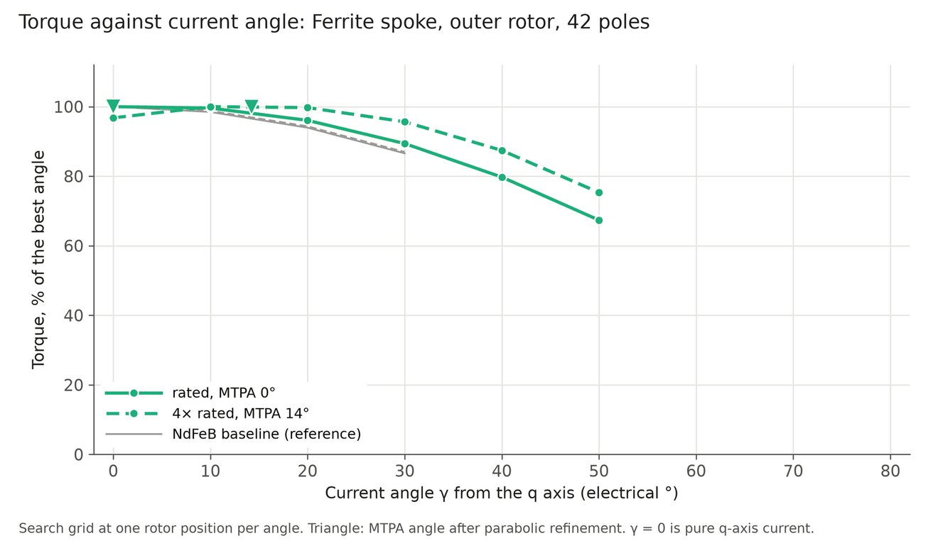
The outer spoke rotor drops into the baseline's own stator. It reaches 41%, because the same stator carries only half the flux it does in the baseline.
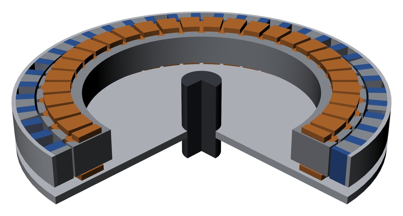
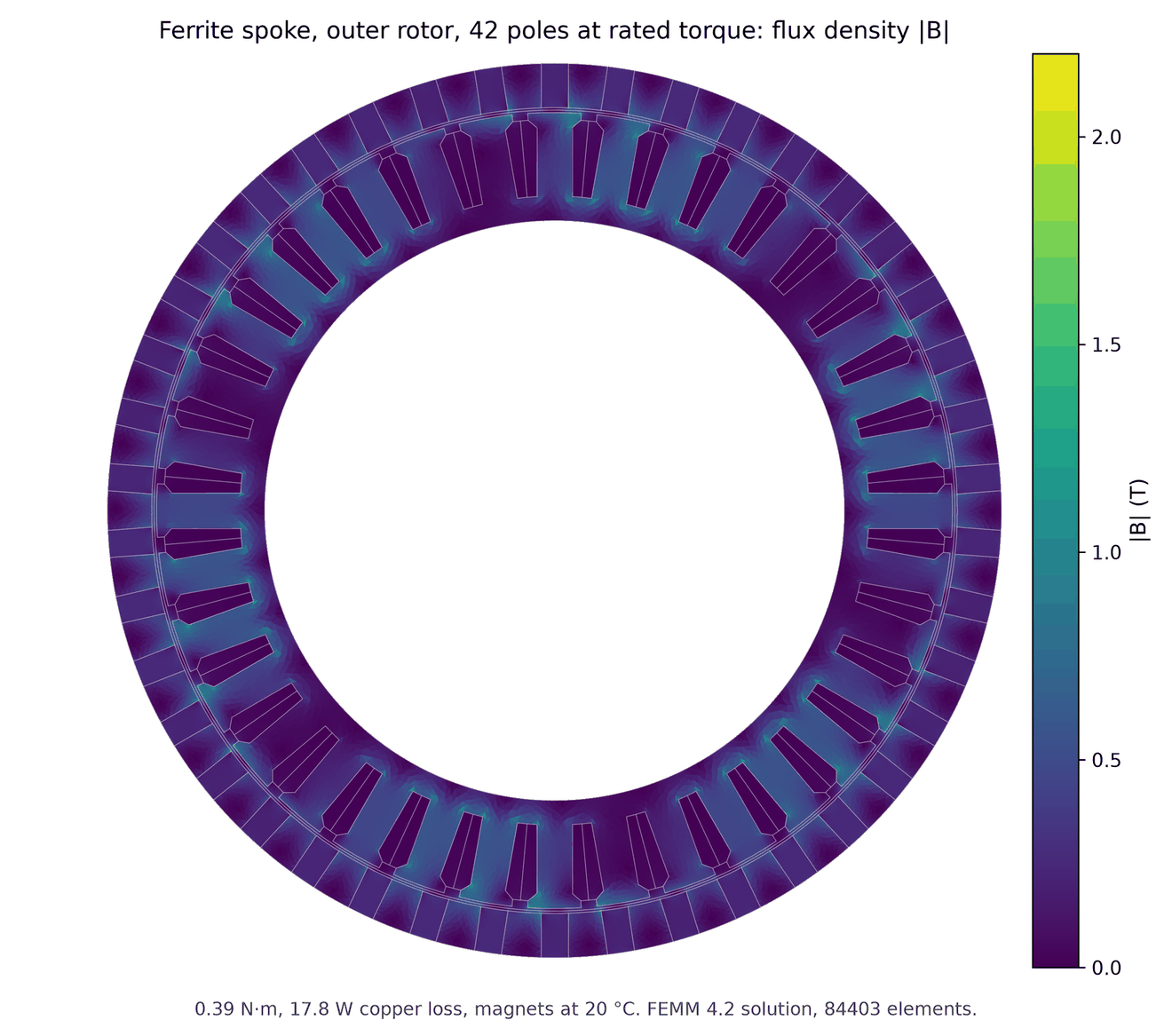
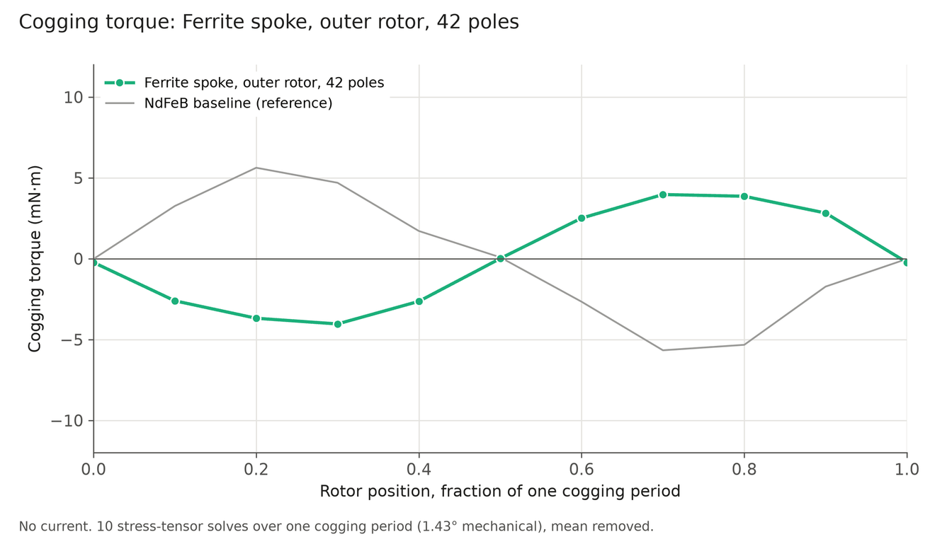
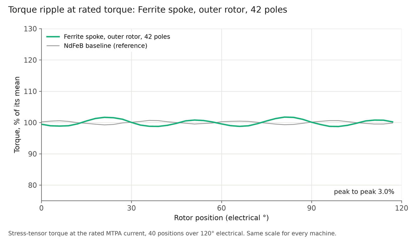
Ferrite-assisted reluctance rotor
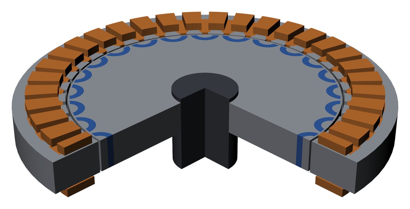
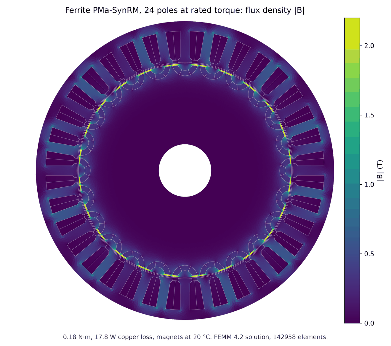
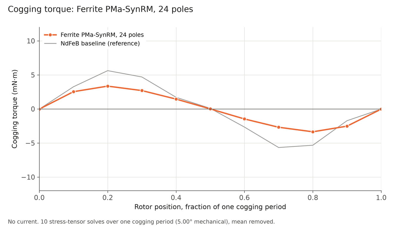
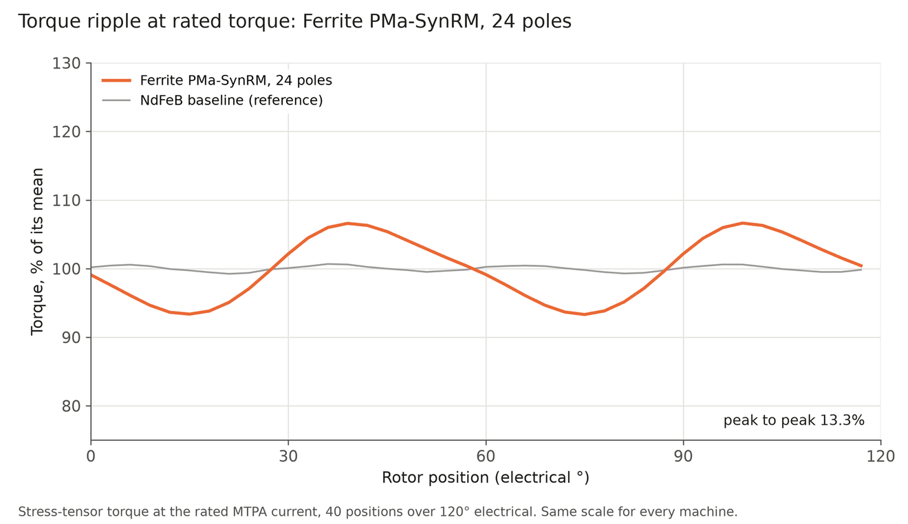
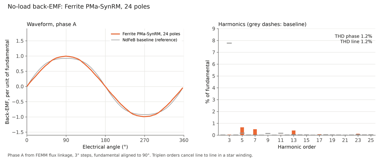
This rotor uses flux barriers to make reluctance torque and puts ferrite in the barriers to add magnet torque. The best of 26 designs, a 24-pole rotor with tooth coils, reaches 0.18 N·m: 10% of the baseline. At this light loading the 0.4 mm ribs at the air gap saturate and take most of the reluctance torque with them, so at rated current all its torque comes from the magnets.
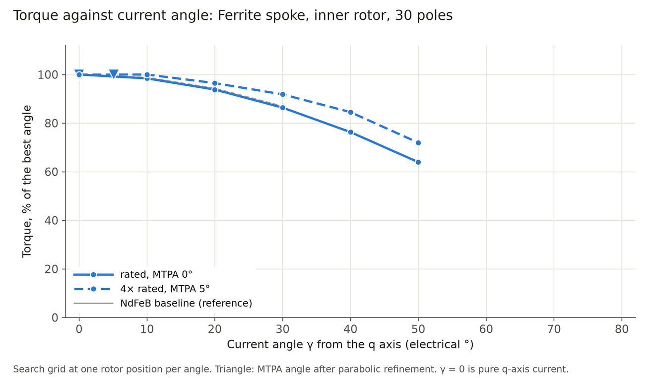
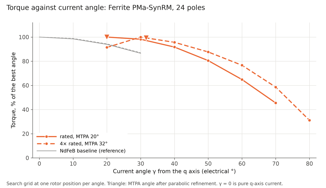
It needs a 20° current angle at rated, has a power factor of 0.64 and ripples 13% at rated and 41% at 4×.
Reluctance rotor, no magnets
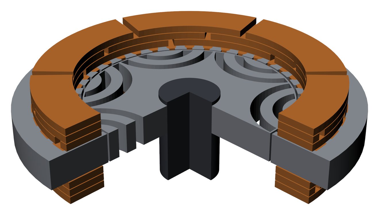
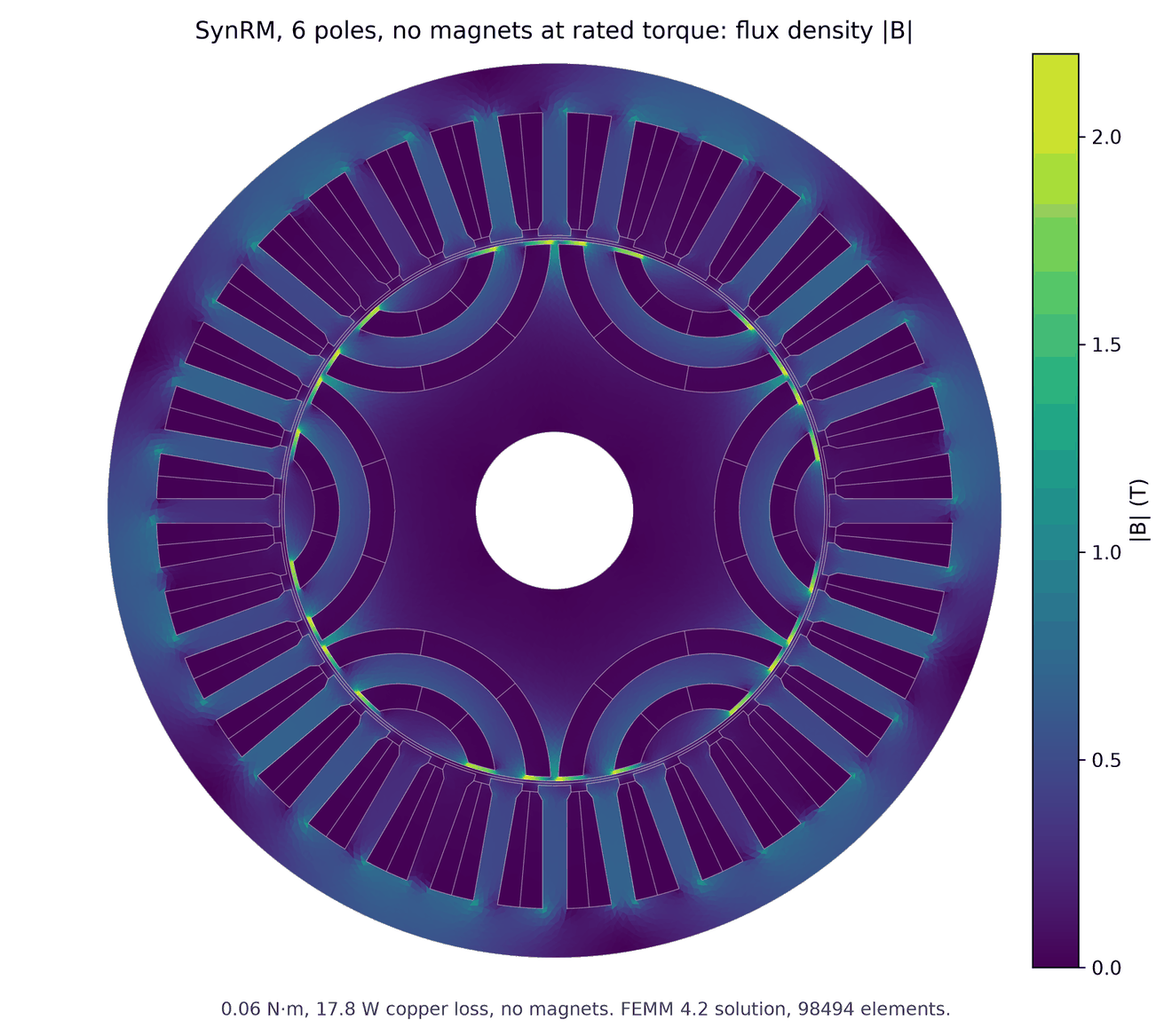
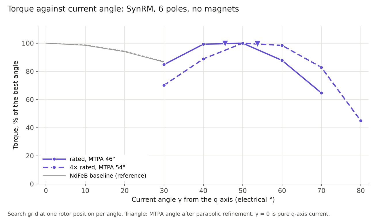
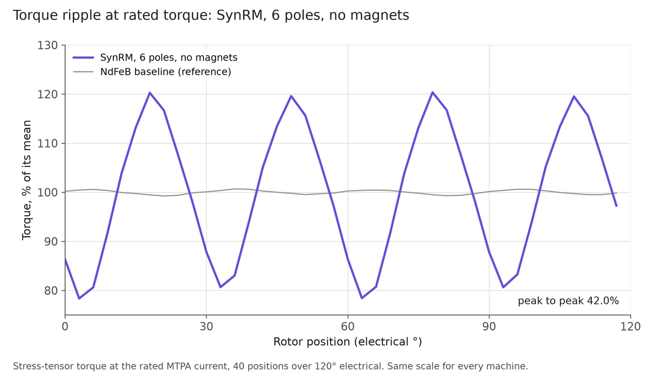
A synchronous reluctance rotor has no magnets at all. The best of 26 designs, a 6-pole rotor with two barriers per pole and a distributed winding, reaches 0.056 N·m: 2% of the baseline. Reluctance torque grows with the square of current, and 17.8 W on an 8 mm stack is a light loading. At 4× current it recovers to 0.78 N·m.
Low pole counts also need distributed windings, whose end turns make the mean turn 4 times longer than a tooth coil's. Its power factor is 0.37 and it ripples 42% at rated without skew, so it does not suit a small joint motor.
Hybrid rotor
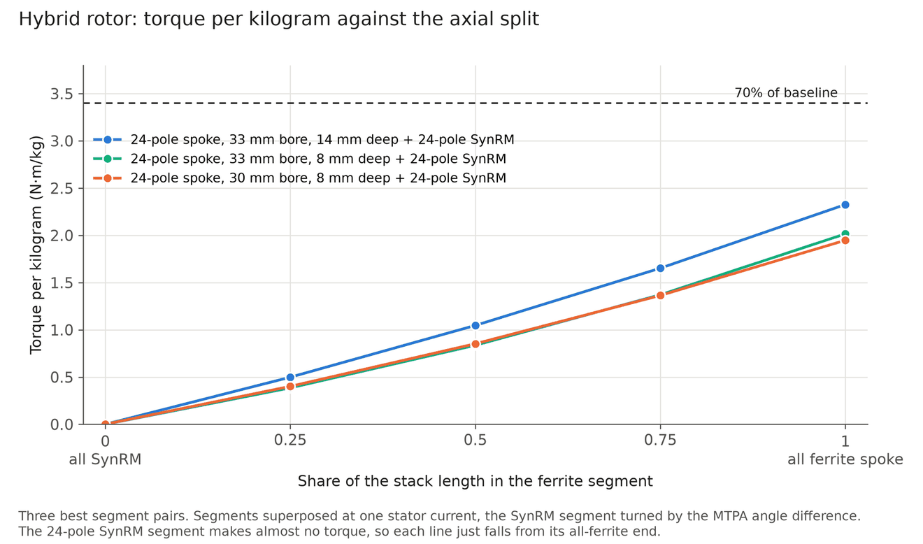
The hybrid stacks a ferrite spoke segment and a reluctance segment on one shaft, offset so their best current angles line up. Its torque per mass is a weighted mean of its two halves, so it can never beat the better one. The best of 219 pairings is 75% spoke and reaches 34% of the baseline; its 24-pole reluctance segment adds almost nothing. It does use less magnet and has less cogging.
3D field views
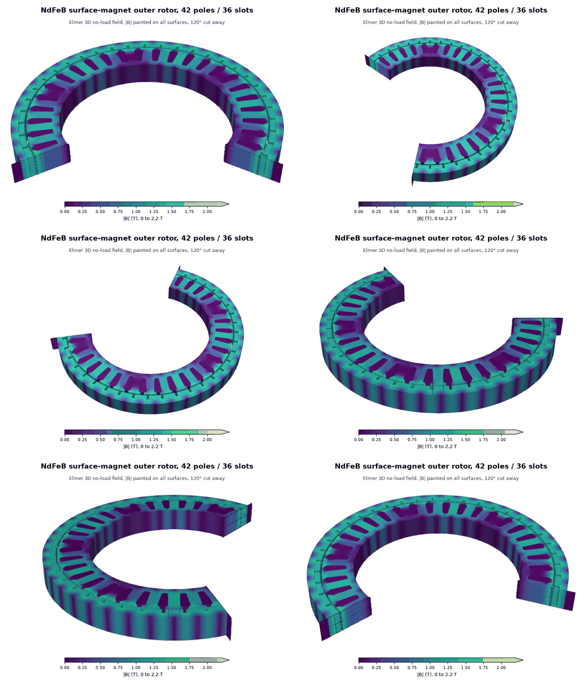
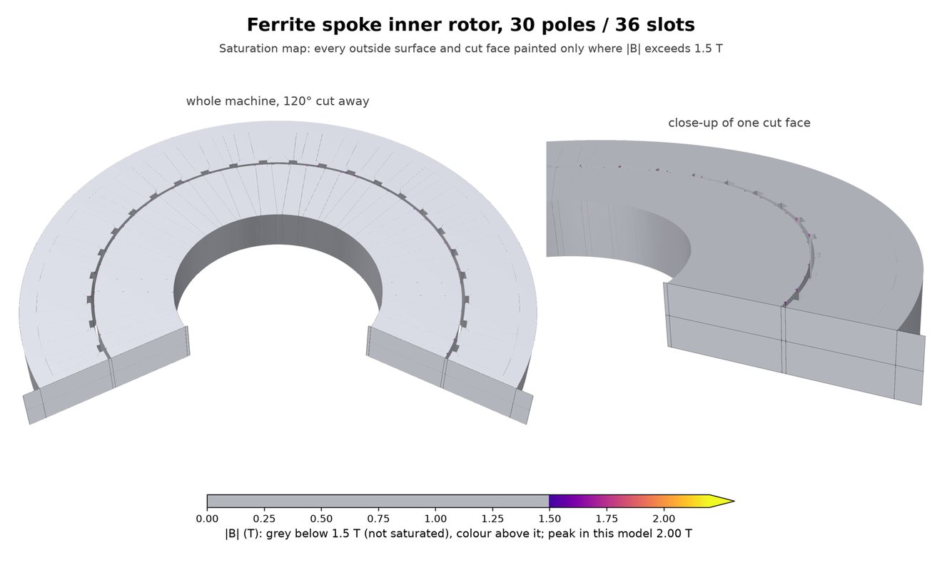
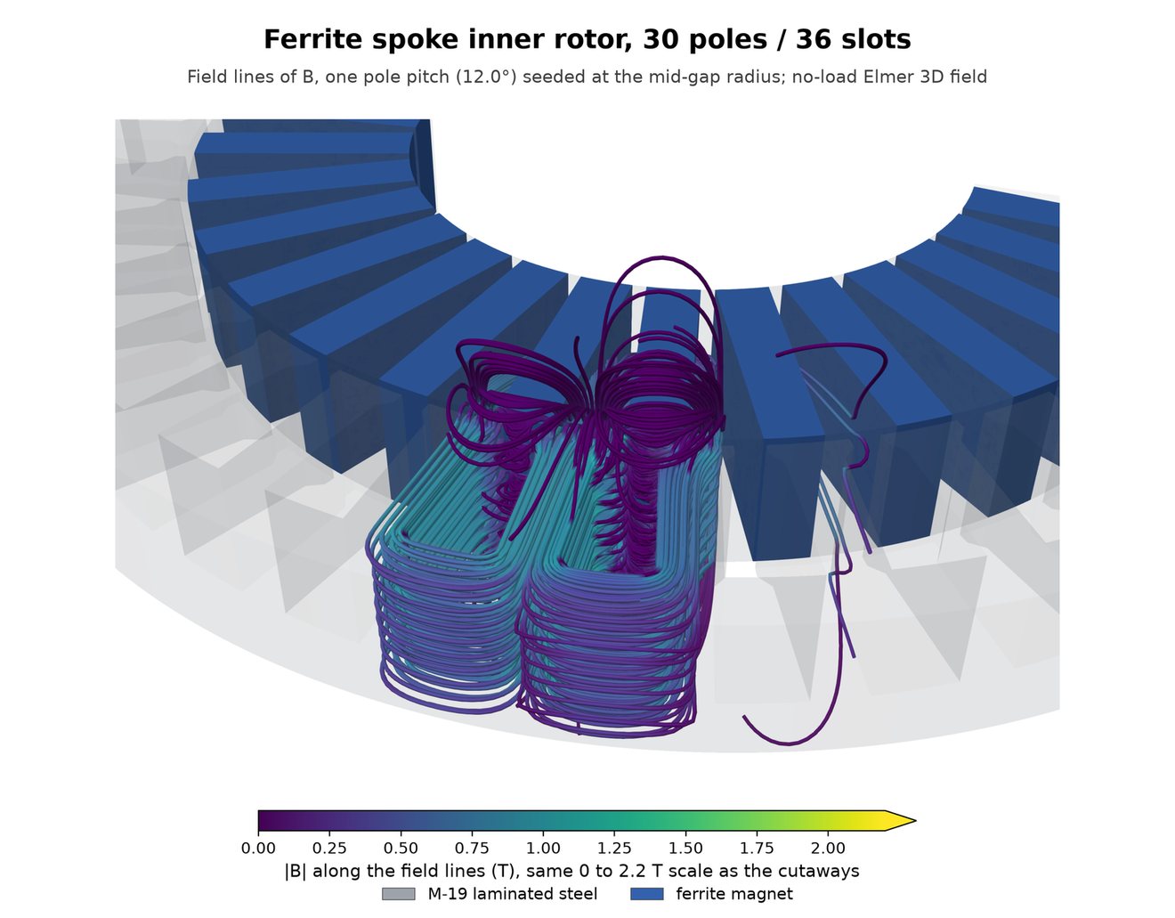
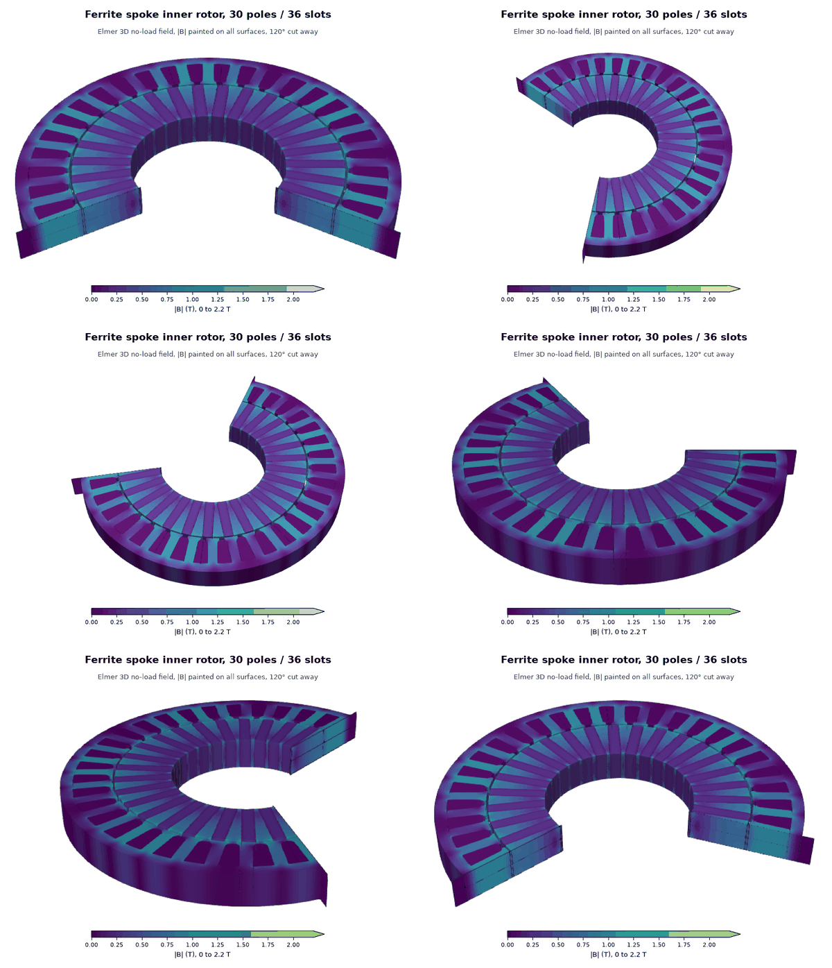
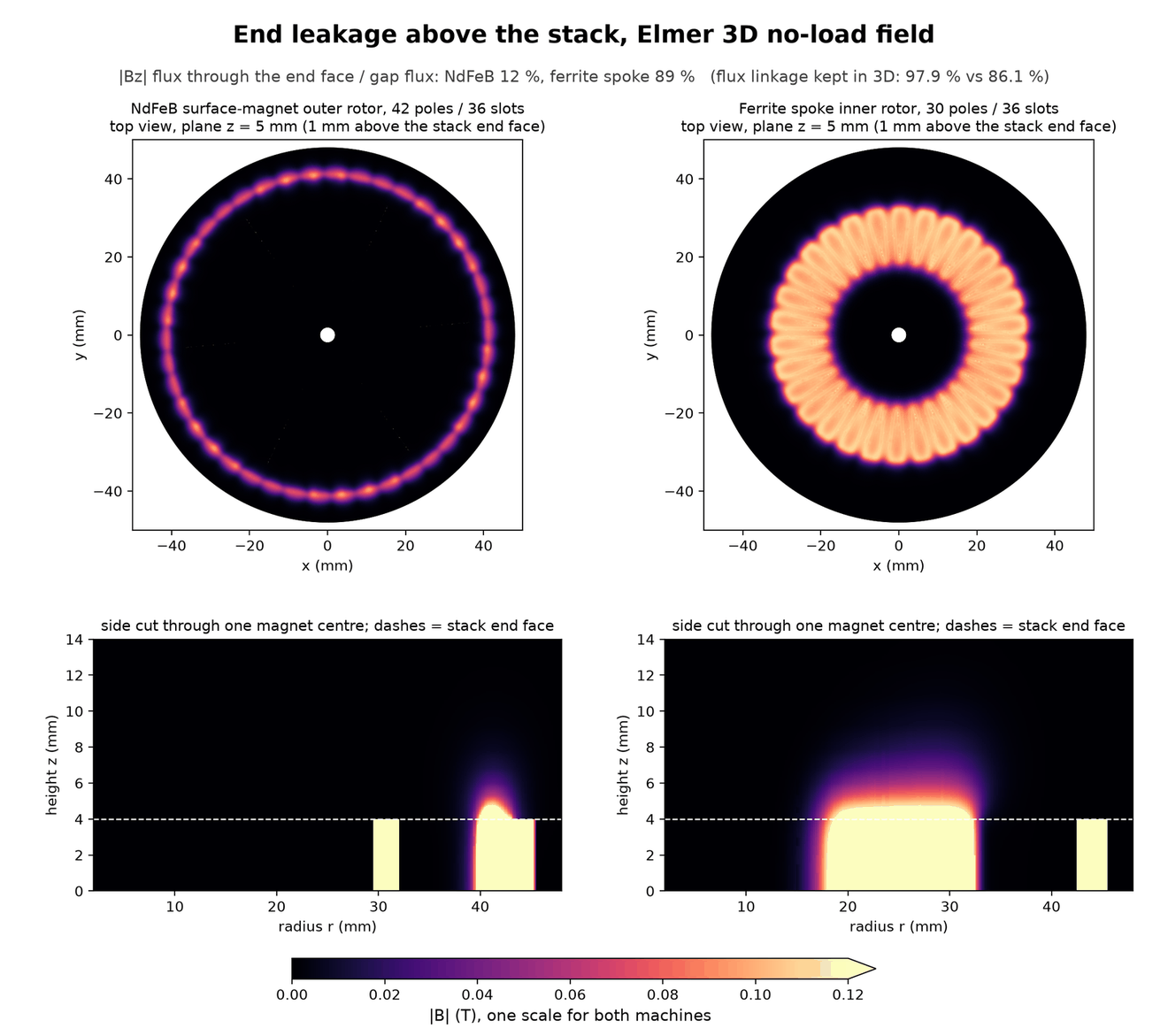
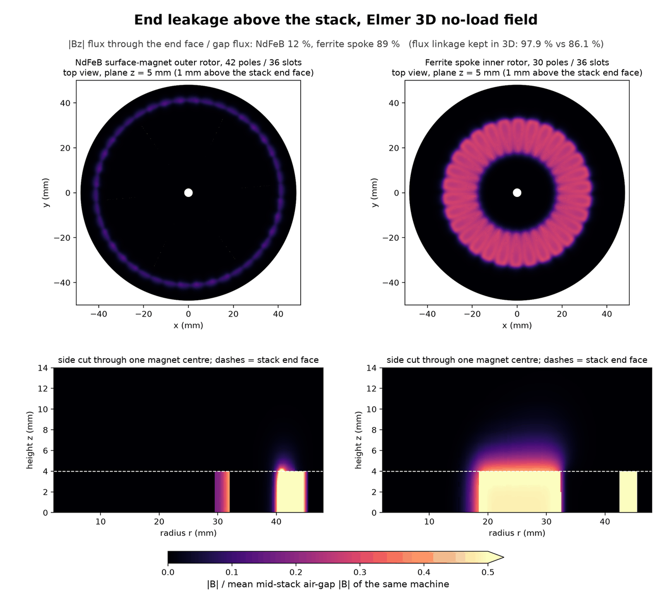
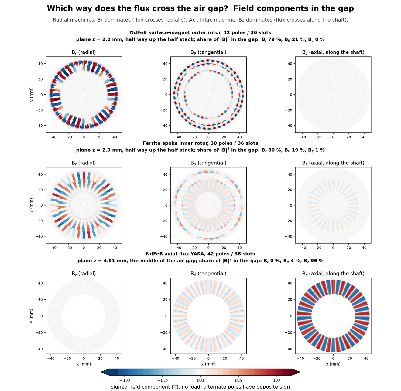
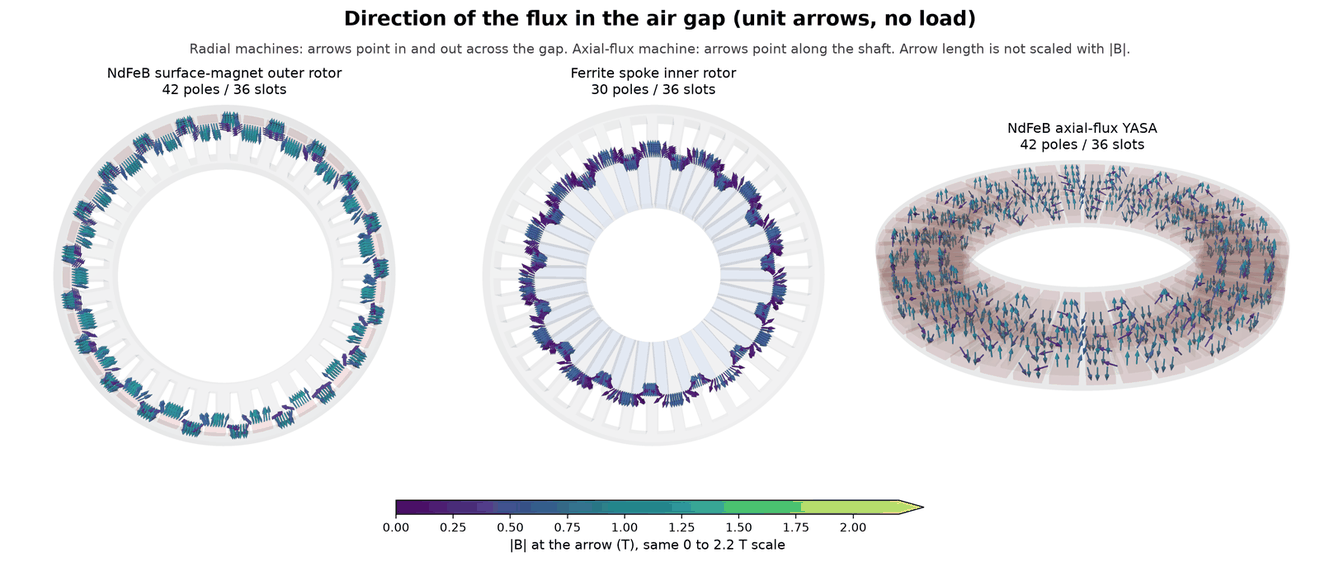
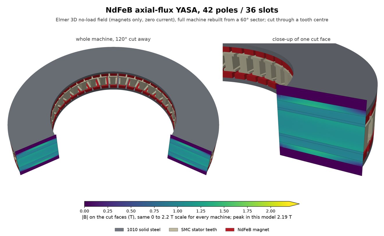
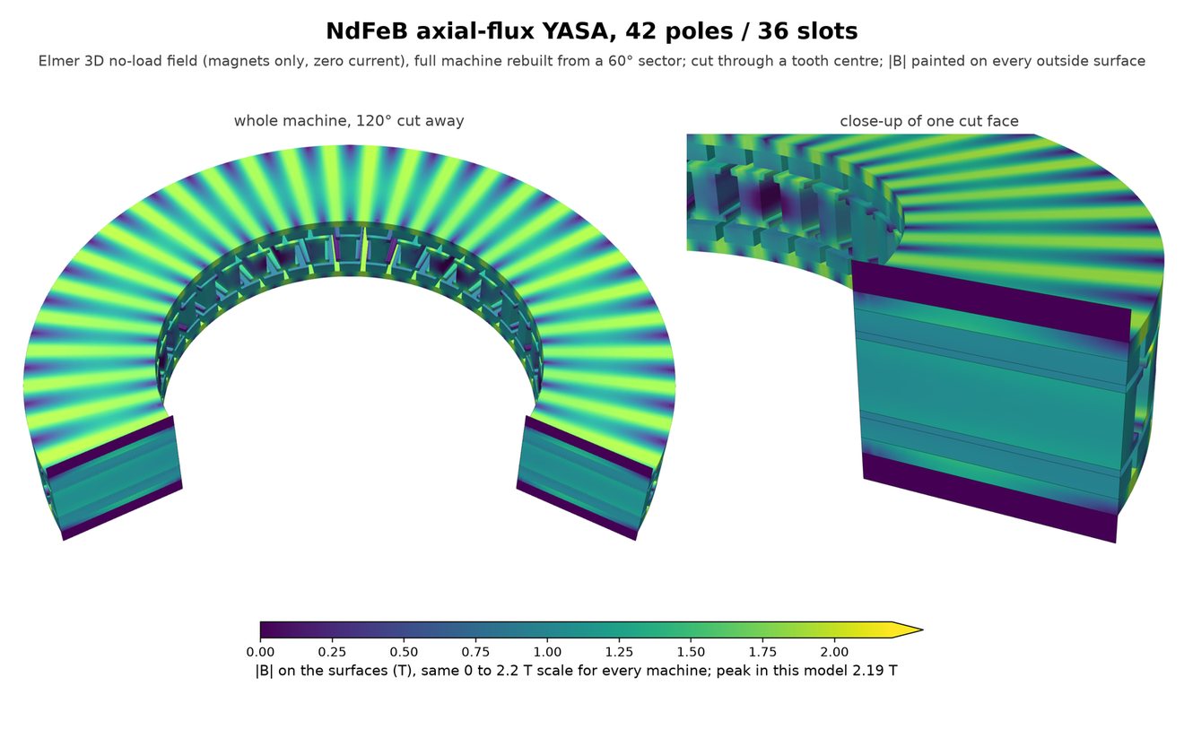
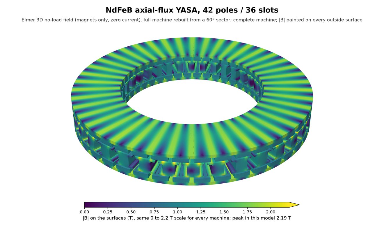
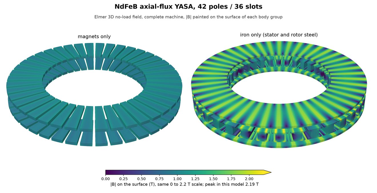
These views come from the Elmer 3D no-load solves used for the end-leakage check. Each solve covers a 60° sector and half the stack, and the full machine is rebuilt from it using the sector's anti-periodic symmetry and the mid-stack mirror. The field is from the magnets alone at one rotor position. Each machine's own 3D views are in its section above.
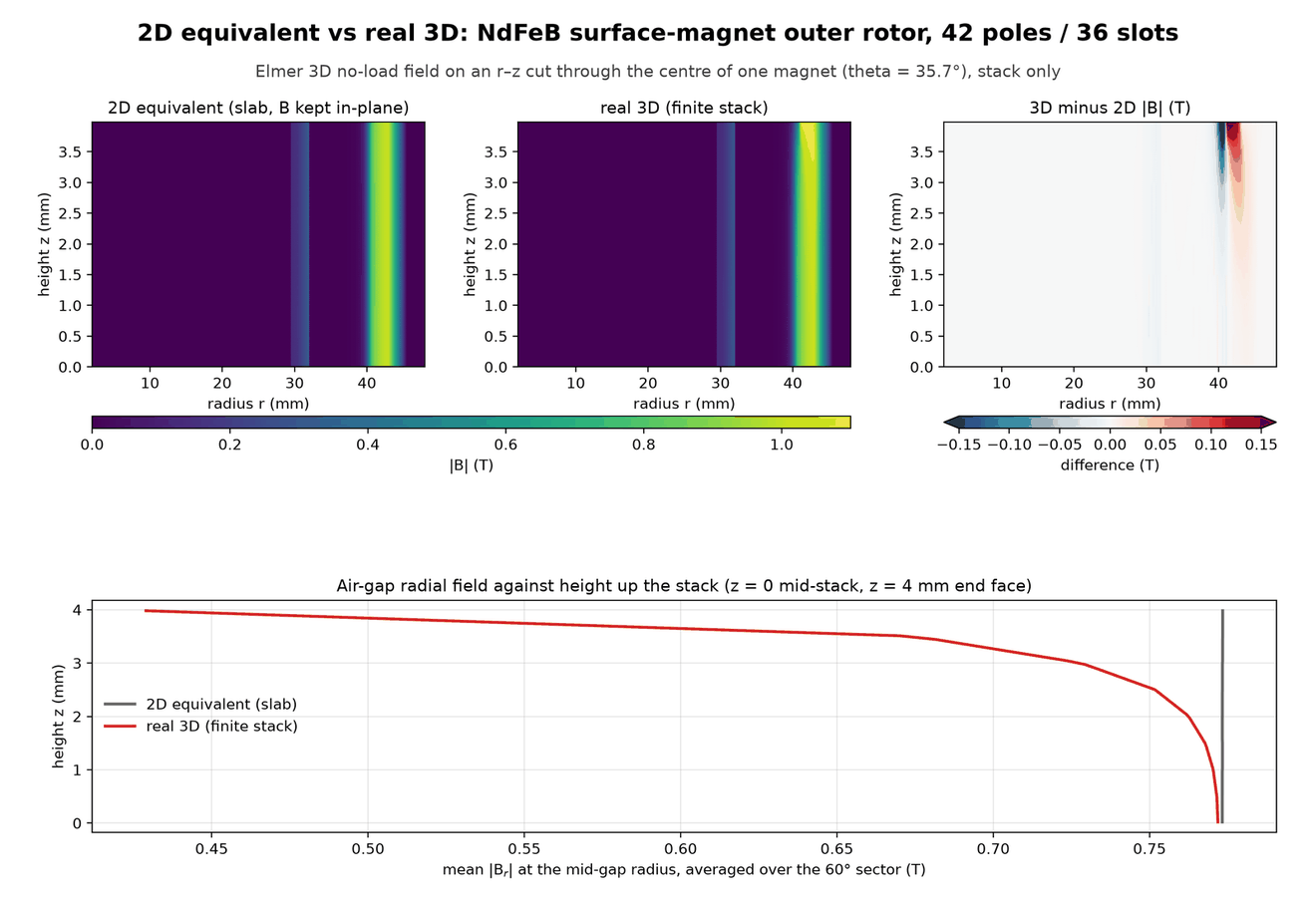
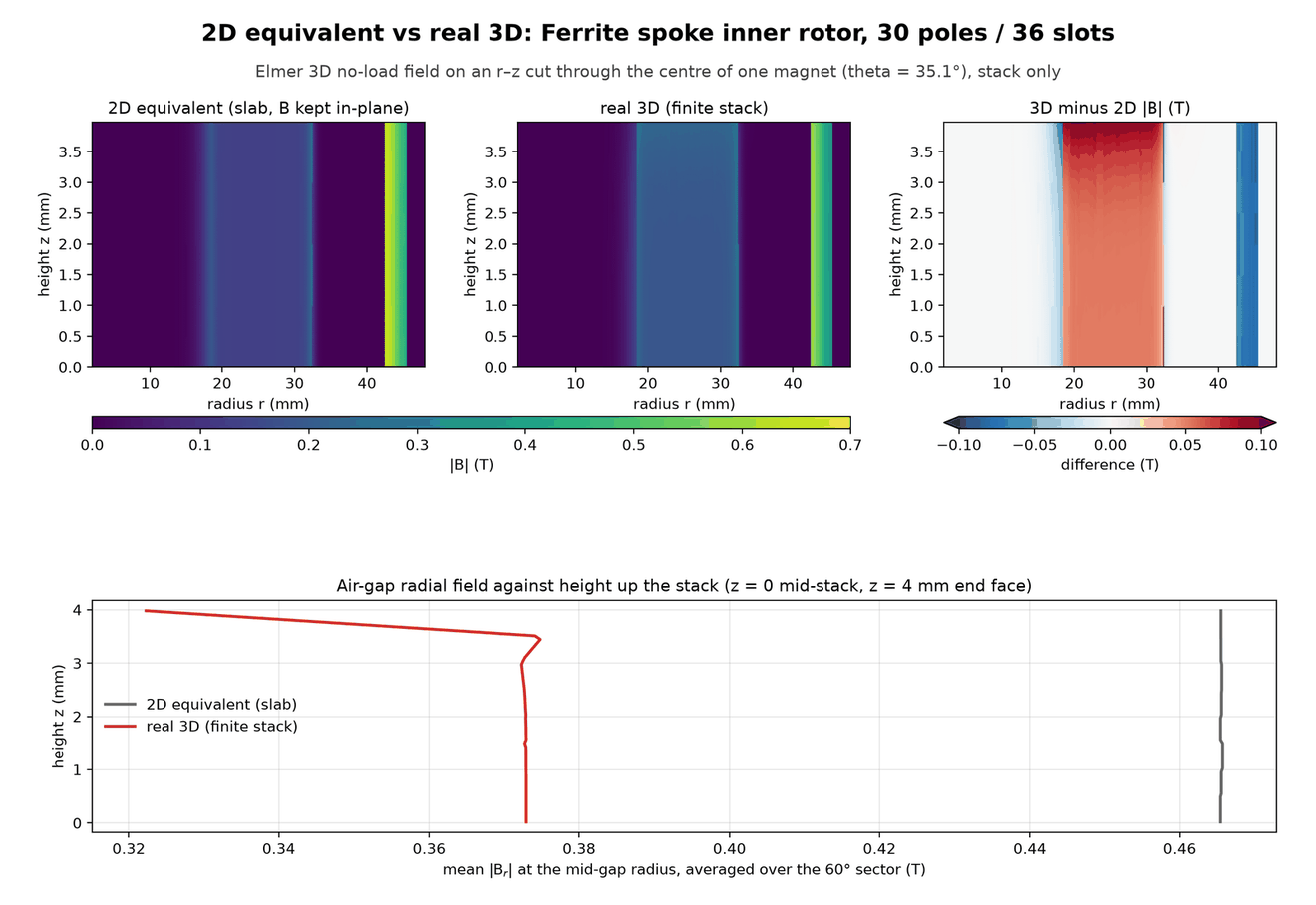
The 3D model shows where the spoke loses its torque. Its magnets push a broad ring of flux out of the rotor ends, and its gap field is about 20% below the 2D model even at mid-stack. The baseline's gap field matches the 2D model at mid-stack and only falls off near the end faces.
Axial flux
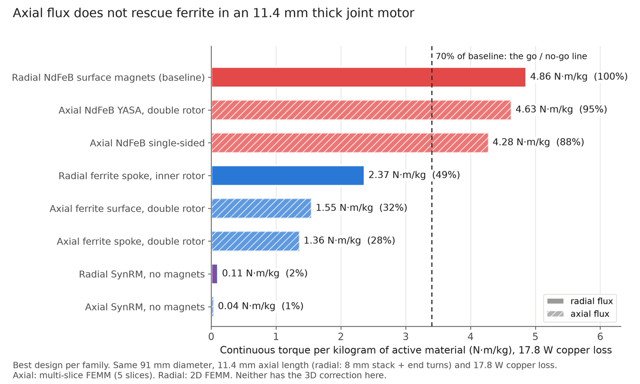
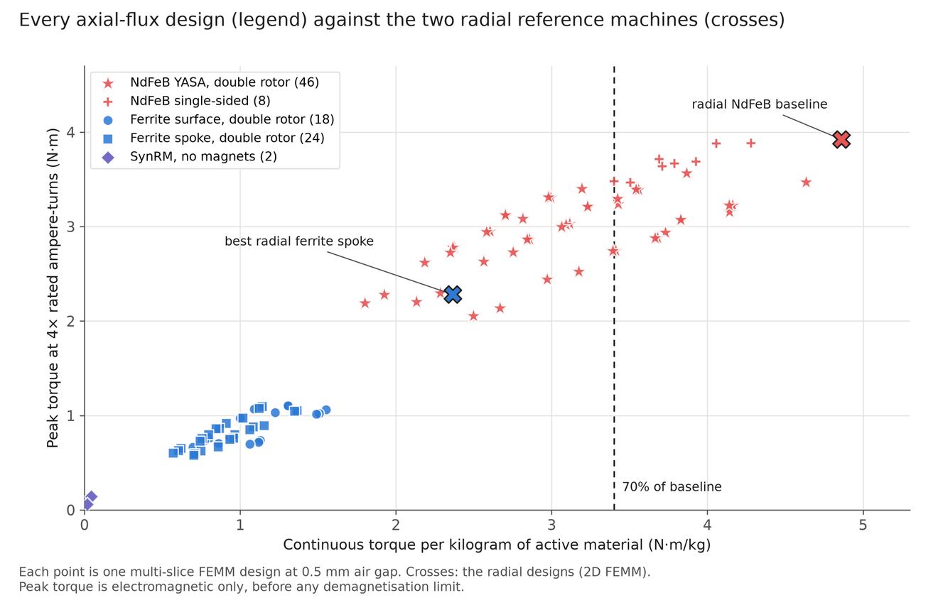
Could an axial-flux layout change the verdict? I swept 99 axial designs in the same package: 91 mm across, 11.4 mm long (the radial machine's 8 mm stack plus its end turns) and the same 17.8 W of copper loss. The families were an NdFeB yokeless and segmented armature (YASA) double rotor, an NdFeB single-sided machine, ferrite surface-magnet and ferrite spoke double rotors, and a magnet-free reluctance rotor. Each design is solved as five FEMM slices at different radii, run on the home cluster, and the best designs were checked in Elmer 3D.
Axial flux makes ferrite worse here. The best axial ferrite design reaches 32% of the baseline's torque per kilogram, against 43% for the radial spoke after its 3D correction. In an 11.4 mm package every millimetre of magnet comes out of the stator, so the thinnest magnets win and the torque stays near 0.27 N·m. The radial spoke's deep magnets cost no stack length.
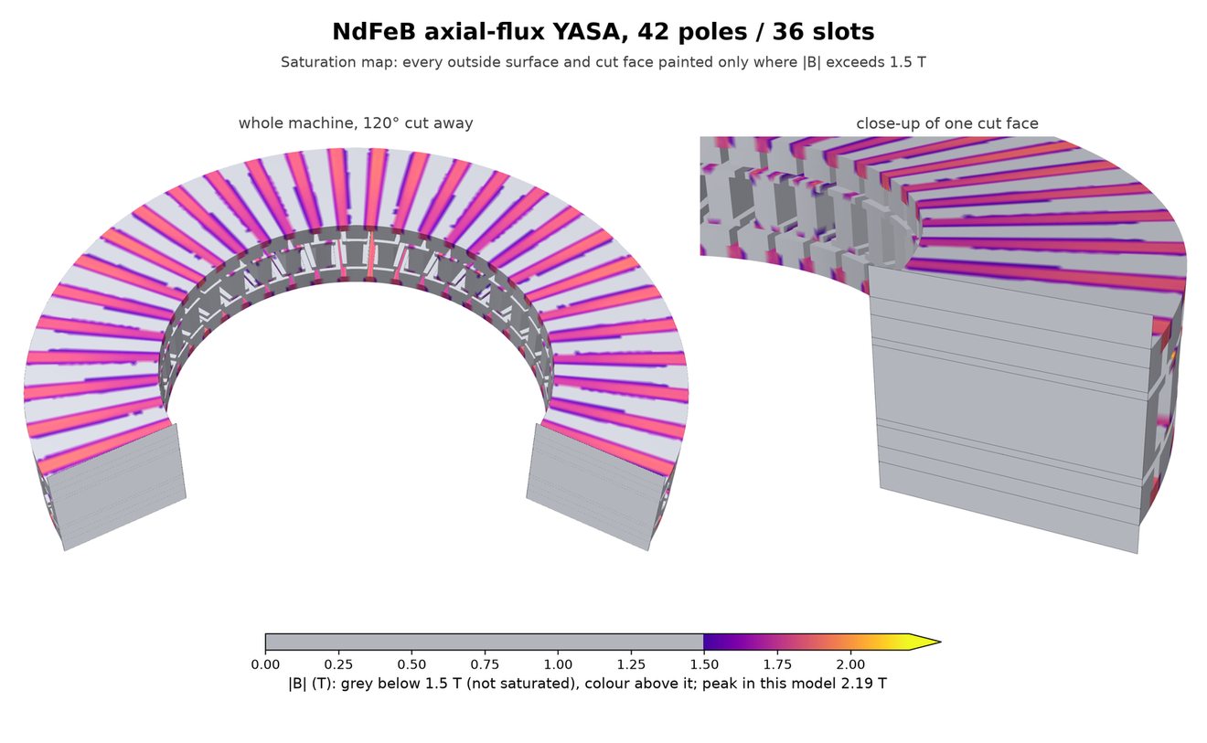
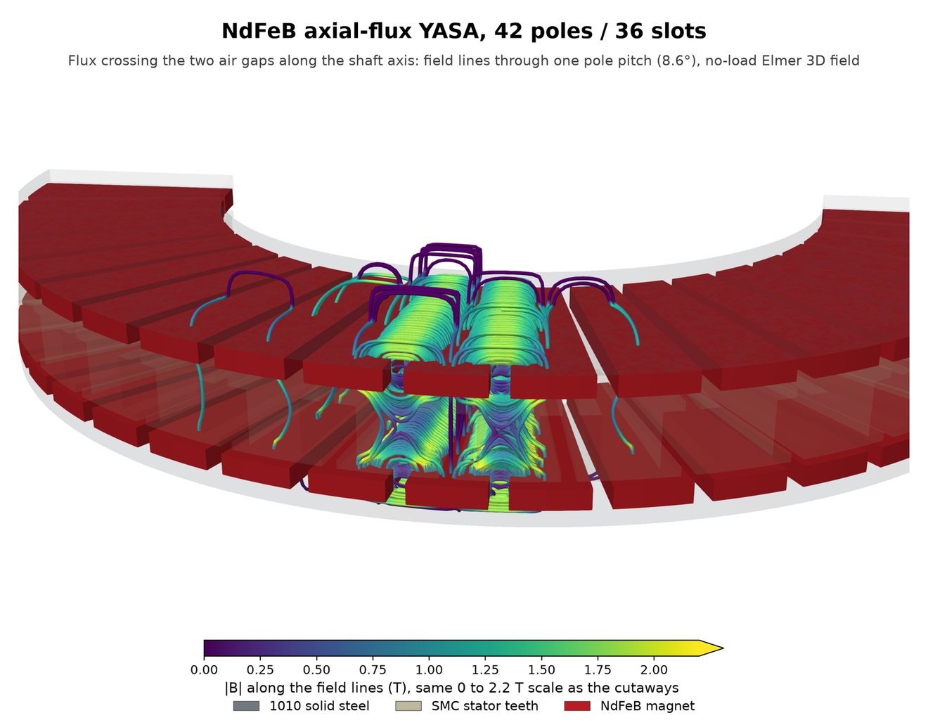
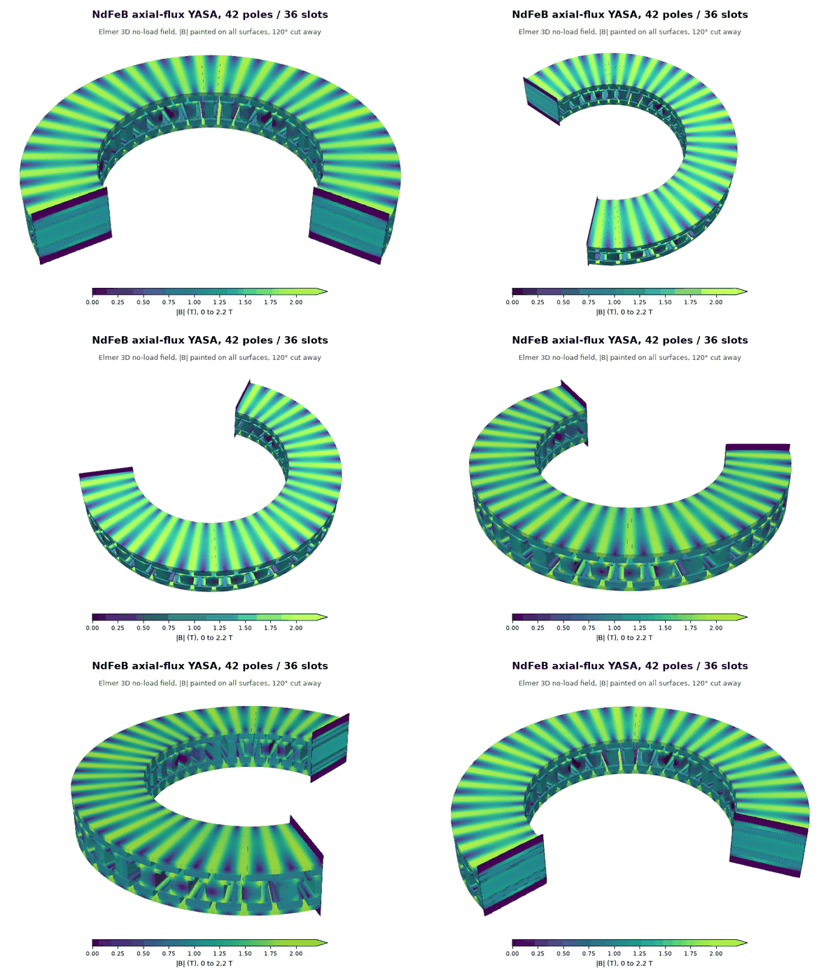
Axial NdFeB does not raise the bar either. The YASA reaches 95% of the radial baseline and the single-sided machine 88%, so the 70% line stays tied to the radial baseline. The axial machines lose little at their edges in 3D: 0.993 for the NdFeB YASA and 0.984 for the best ferrite design, against 0.861 for the radial spoke.
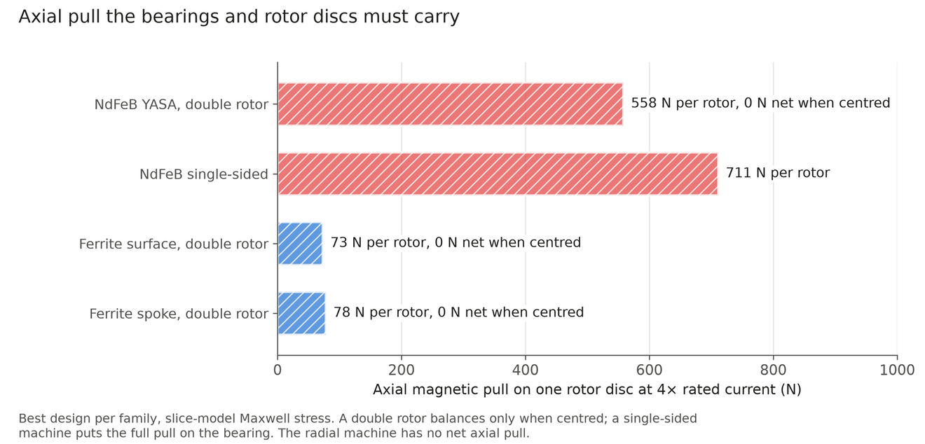
Axial pull becomes a design load. At peak current each NdFeB YASA rotor is pulled towards the stator with 558 N. A double rotor cancels that only when centred, and off centre it is pushed further with about 1.8 N per µm. A single-sided machine puts 711 N on its bearing. Ferrite pulls about 75 N. Widening the air gap from 0.5 mm to 0.75 mm costs 20% of the torque, so the gap has to be held tightly against that pull.
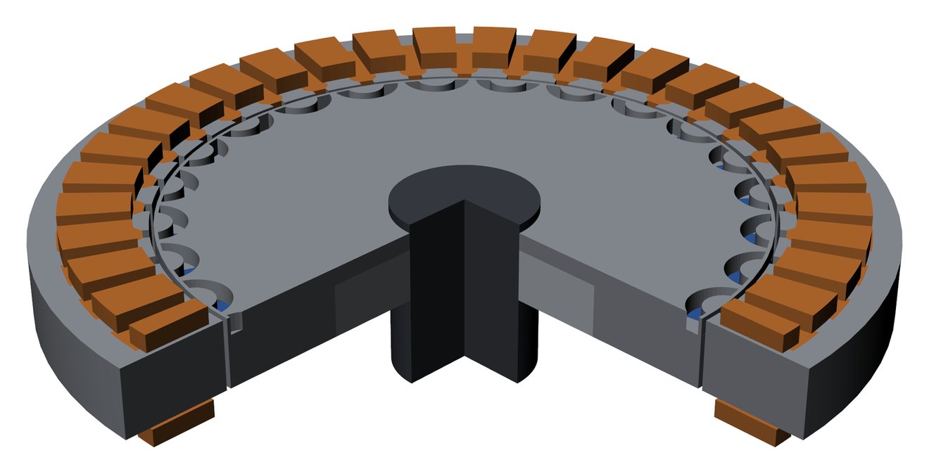
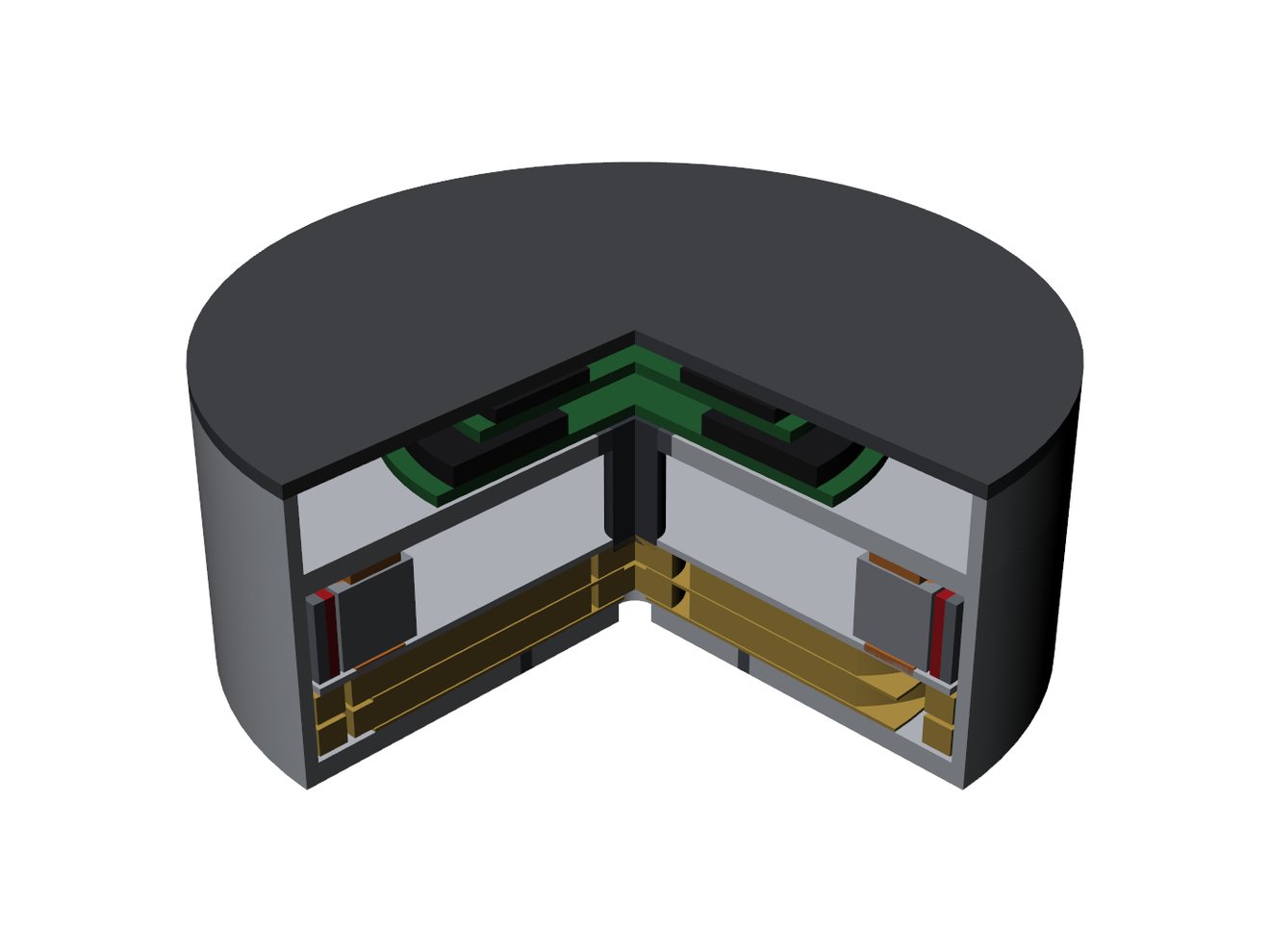
The 3D views below are the NdFeB YASA design with 36 slots and 42 poles used for the Elmer check, not the best YASA in the sweep. Its coils are not modelled, so none are drawn.
Method and checks
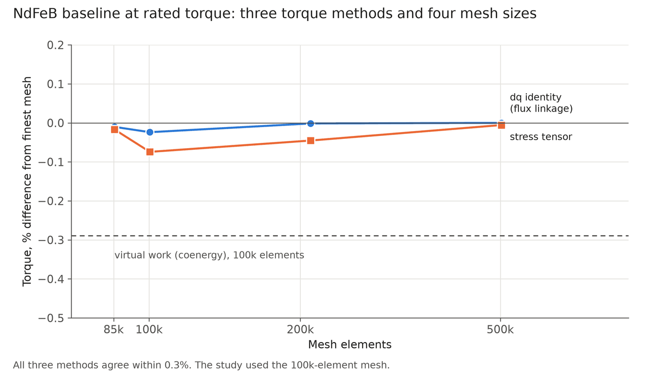
Every model is the full 360° machine in FEMM 4.2, run headless on my home Linux server. Torque at each current comes from a search over current angle. Three torque methods agree within 0.3% on the baseline, and torque moves 0.02% between 100,000 and 500,000 mesh elements. For the 3D check, Elmer solves a 60° sector of the baseline and the best spoke. A 2D-equivalent version reproduces FEMM's flux linkage within 0.6%. The finite 8 mm stack then gives the end-leakage factor: 0.979 for the baseline and 0.861 for the spoke. Laminations, the far boundary and a finer axial mesh each move it by 0.3% or less.
The stator and magnet dimensions are estimates of the WGG8108, not measurements. The 2D models leave out spoke bridges and iron losses, which would both lower the ferrite numbers further.
Per-joint actuators on MABEL
The sections above use one stator size. This section asks the same question for the joints of the MABEL robot, with a separate actuator for each joint. Arm and torso actuators are sized per joint from a library of 145 FEMM motor designs: NdFeB surface-magnet outer rotors against ferrite spoke inner rotors. Each actuator is a motor, a gearbox, a housing and my 48 V board stack, chosen together. Each set is sized again with its own masses and gearbox inertia, so a heavier shoulder actuator raises the torso load. The study calls this coupled sizing. The main case limits the gearbox to a two-stage planetary of at most 64:1. The lift, head and hands are stock MABEL parts. The swerve drive in the base was not changed in any variant, because it was not in the design scope of this feasibility study.
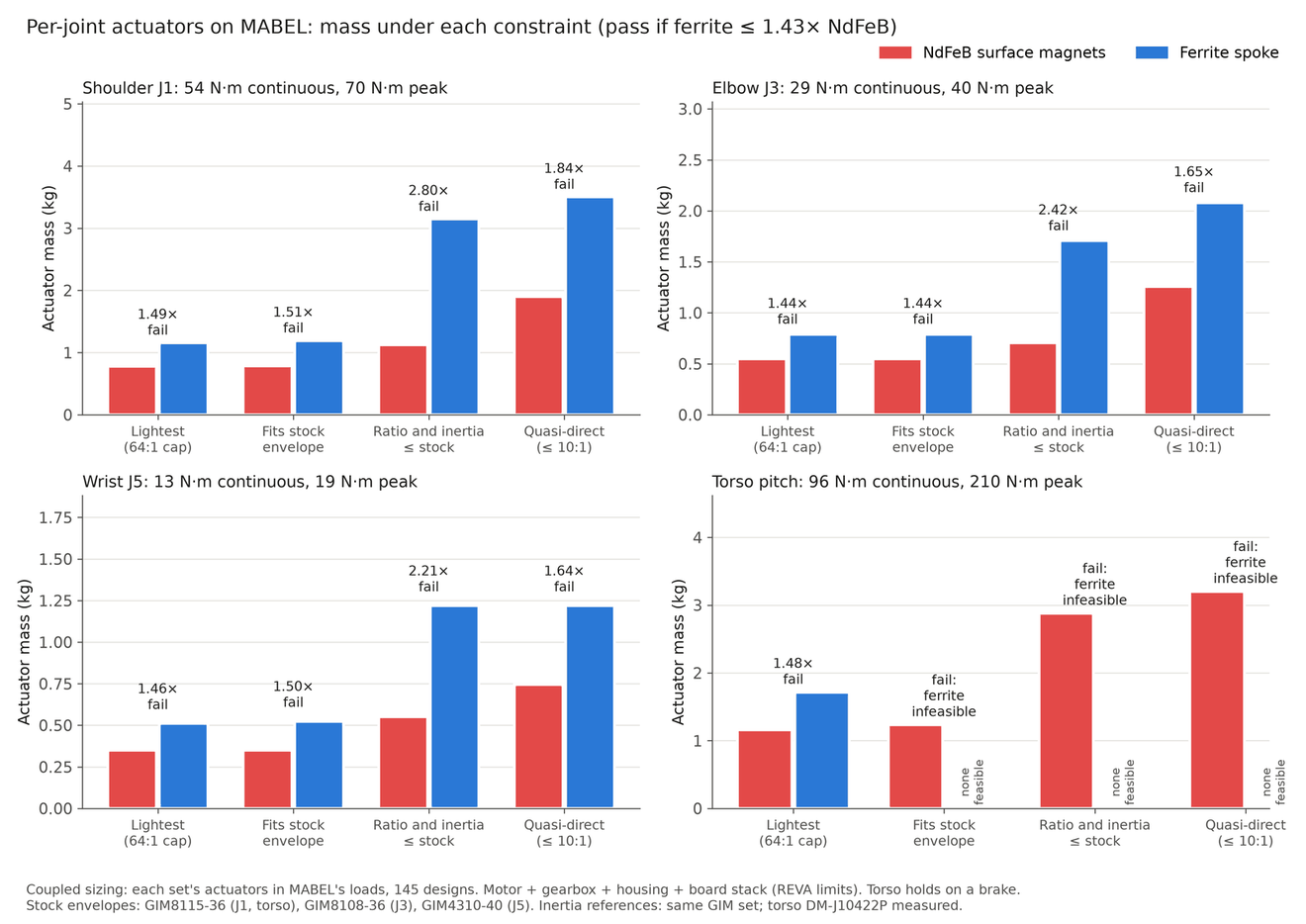
Before any results, the pass line was set at ferrite weighing at most 1.43 times the NdFeB actuator, which is the same 70% of NdFeB torque per kilogram used above. This is a judgement line from the original brief, chosen before the results. It is not computed. In the main case ferrite fails it at all four joints, with ratios of 1.44 to 1.49. One arm's actuators weigh 3.68 kg with NdFeB and 5.38 kg with ferrite.
The break-even cutoff is the line at which a joint would flip, and for the main case it is 67% to 69%. The same picks pass at a 60% or 65% line and fail at 70%, 75% and 80%. The ratio depends on how much gearing is allowed, as the next section shows. The whole-robot MuJoCo check of these sets is on the humanoid upper body page.
What stock means. In the mass and size comparisons, stock is MABEL's own DAMIAO actuators. In the MuJoCo and Simulink comparisons, stock is the GIM reference set (GIM8115-36, GIM8108-36 and GIM4310-40), because the electrical data of MABEL's DAMIAO actuators is not modelled.
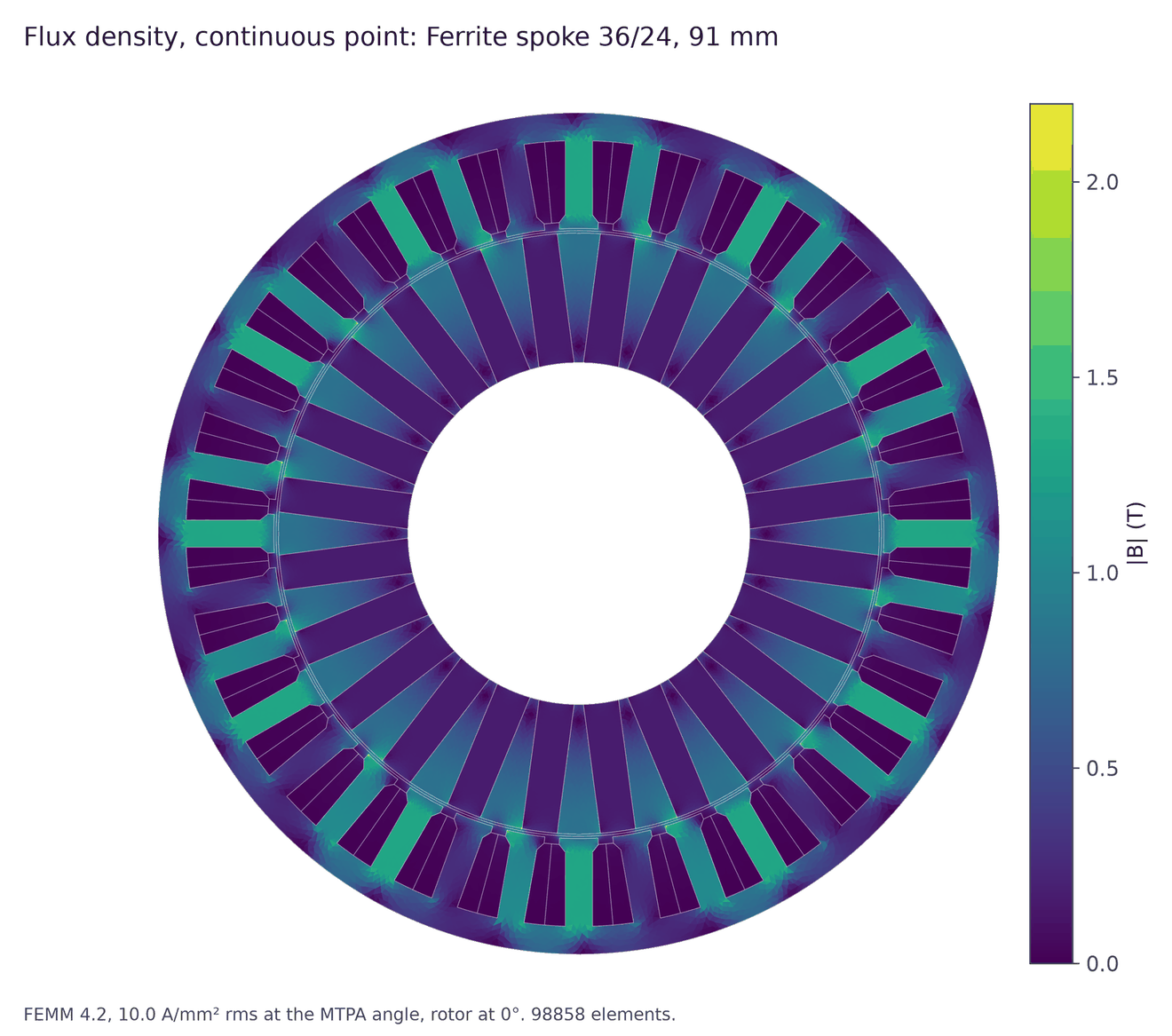
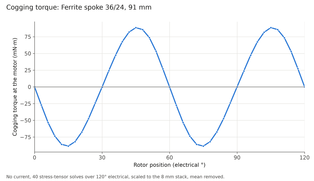
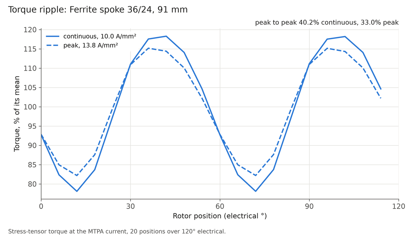
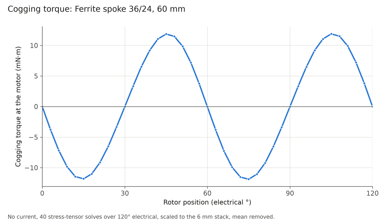
Cogging warning. The mass-only optimiser chose 36-slot, 24-pole ferrite spokes for most of the ferrite arm joints, including J1, J3 and J5 here. Those motors have a cogging torque of 20% to 38% of their continuous torque and a torque ripple of up to 45%, against 3.5% to 7.6% for 30-pole spokes. The library sweep did not compute cogging, so the optimiser could not see it. A low-cogging ferrite set with no 24-pole motors weighs about 1% more (5.45 kg instead of 5.38 kg for one arm in the main case) and gives the same verdict at every joint. The new 3D flux overlays at the end of this page use the low-cogging picks. The 24-pole ferrite plots here retain the original mass-only result; they are not the recommended design.
The per-pick Elmer 3D no-load solves are complete. Painted field views, field lines and the finite-stack end-leakage checks are at the end of this page. Torque against current angle, PWM ripple, temperature and cold demagnetisation are separate loaded-motor checks.
| Joint | NdFeB pick (mass, size) | Ferrite pick (mass, size) | Ferrite / NdFeB | Break-even cutoff |
|---|---|---|---|---|
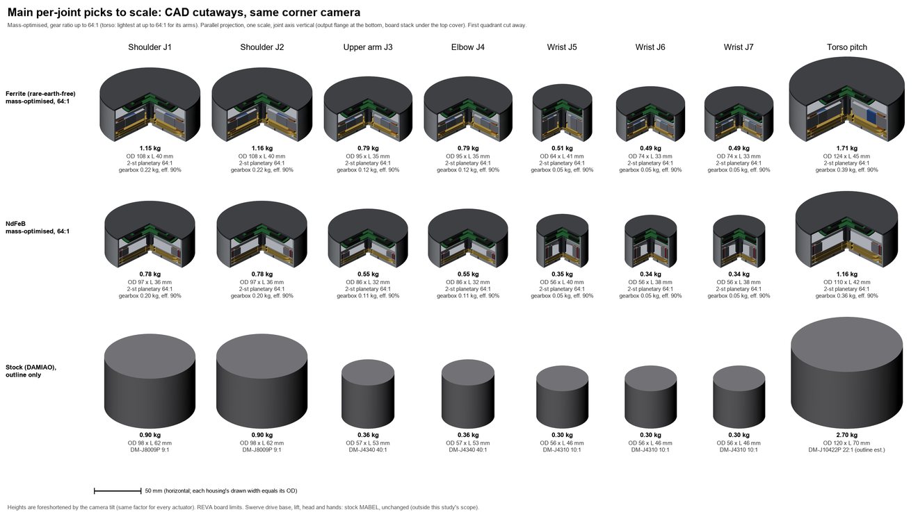
| Shoulder J1 | 0.78 kg, 97 × 36 mm | 1.15 kg, 108 × 40 mm | 1.49 fail | 67% |
| Upper arm J3 | 0.55 kg, 86 × 32 mm | 0.79 kg, 95 × 35 mm | 1.44 fail | 69% |
| Wrist J5 | 0.35 kg, 56 × 40 mm | 0.51 kg, 64 × 41 mm | 1.46 fail | 69% |
| Torso pitch | 1.16 kg, 110 × 42 mm | 1.71 kg, 124 × 45 mm | 1.48 fail | 68% |
Every pick above is a two-stage planetary at 64:1. J2 repeats J1 and J4 repeats J3. The picks for J6 and J7 differ slightly from J5. Sizes are the outer diameter and length of the whole actuator.
Ferrite to NdFeB mass ratio in every case
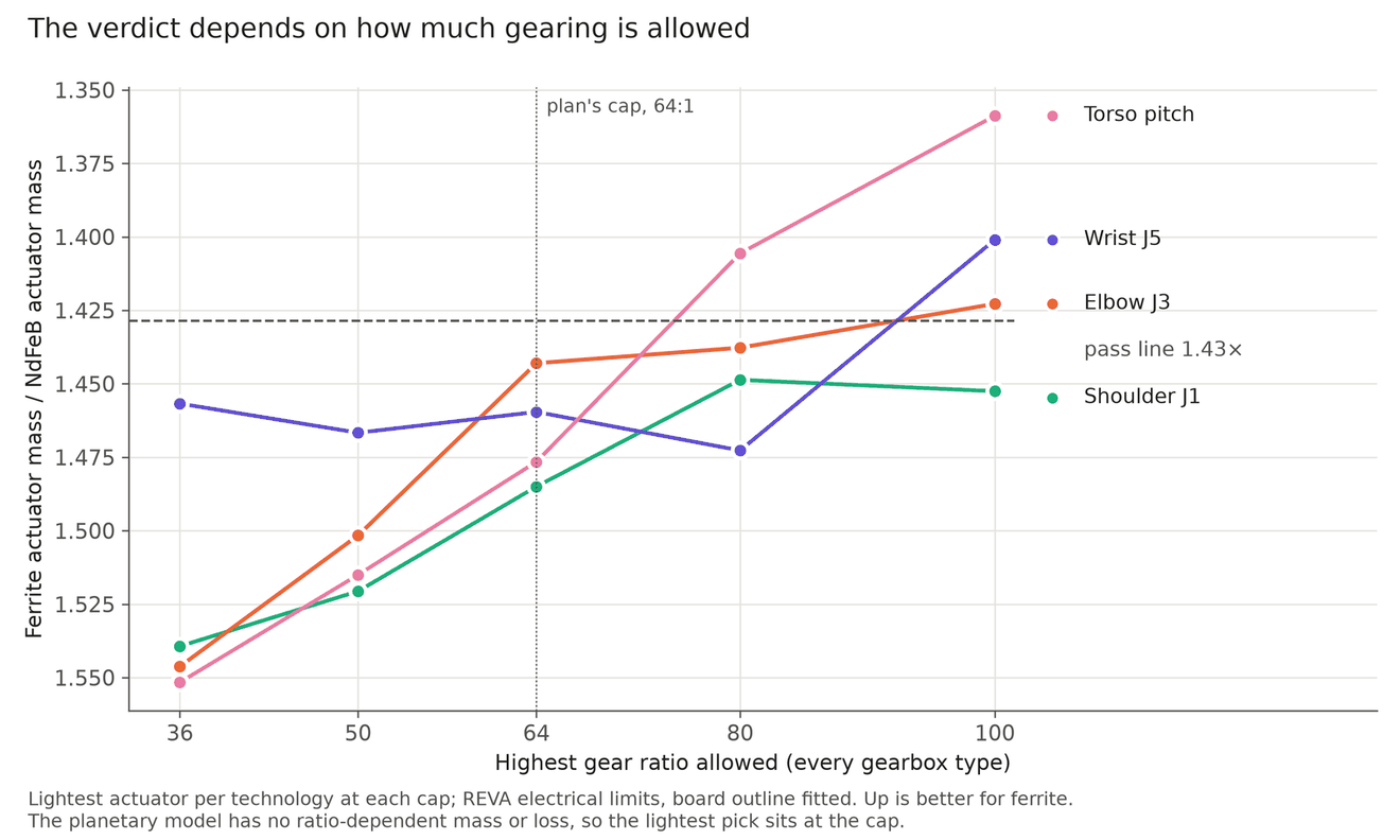
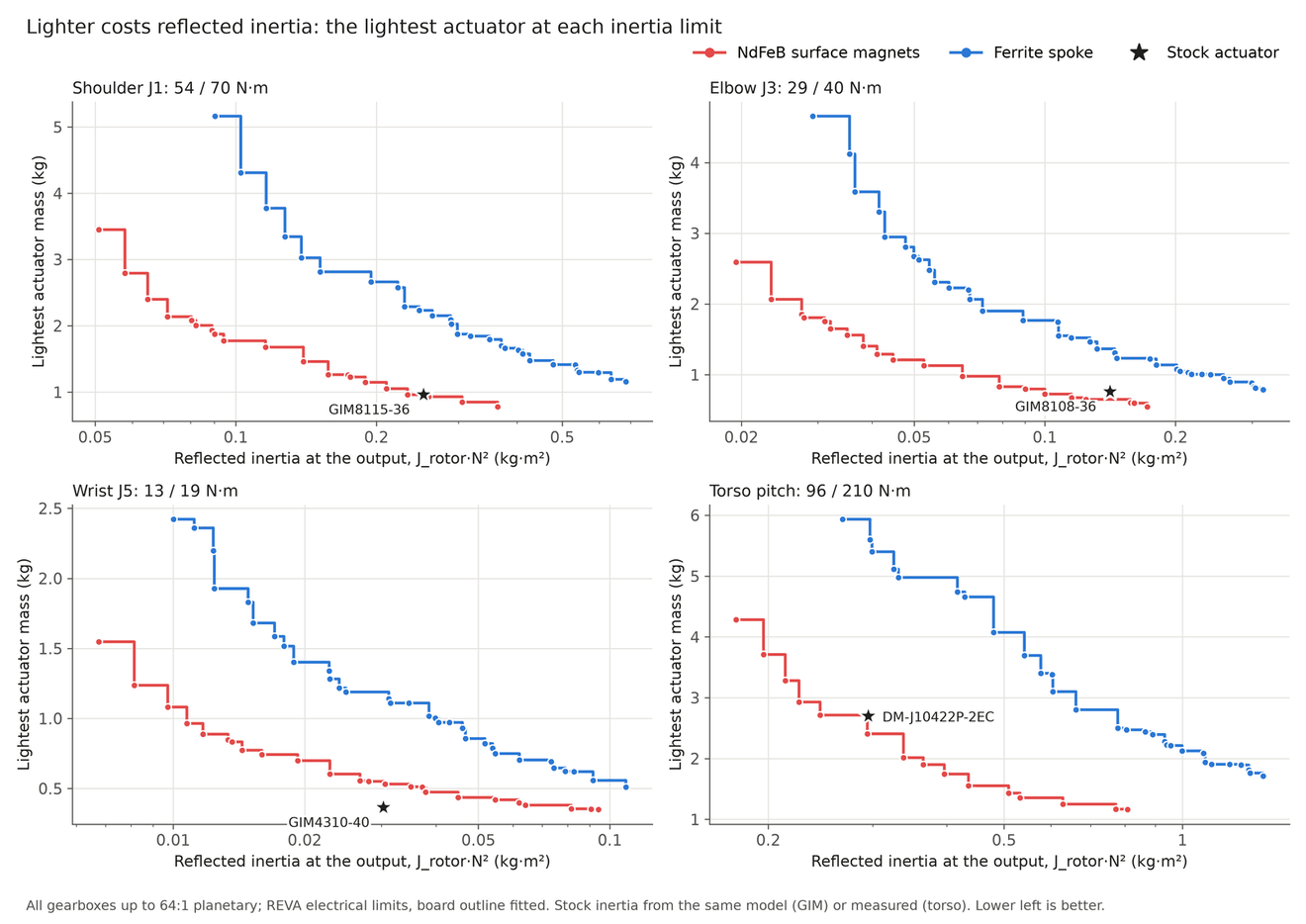
The ratios come from the coupled sizing, and a pass is 1.43 or less. The mass_100 case is the only one where ferrite passes at all four joints, but the whole-robot check on the humanoid page fails that ferrite set. The backdrive and QDD cases limit the gear ratio and the reflected inertia, which is where the ferrite actuators grow the most. In the mass_50 case the ferrite J3 and J5 picks switch to a 160:1 strain wave gearbox, so that comparison is a strain wave against a planetary. A torso entry reads ferrite infeasible when no ferrite actuator can meet that set's own torso constraint.
| Case | J1 | J3 | J5 | Torso |
|---|---|---|---|---|
| main (64:1) | 1.49 fail | 1.44 fail | 1.46 fail | 1.48 fail |
| mass_64 | 1.49 fail | 1.44 fail | 1.46 fail | 1.48 fail |
| mass_50 | 1.52 fail | 1.45 fail | 1.36 pass | 1.52 fail |
| mass_100 | 1.40 pass | 1.42 pass | 1.40 pass | 1.36 pass |
| mass_64_reva66 | 1.48 fail | 1.44 fail | 1.35 pass | 1.47 fail |
| size | 1.51 fail | 1.44 fail | 1.50 fail | ferrite infeasible |
| backdrive | 2.80 fail | 2.42 fail | 2.21 fail | ferrite infeasible |
| backdrive_modelref | 2.66 fail | 2.14 fail | 2.21 fail | ferrite infeasible |
| qdd | 1.84 fail | 1.65 fail | 1.64 fail | ferrite infeasible |
Machines for the shoulder J1
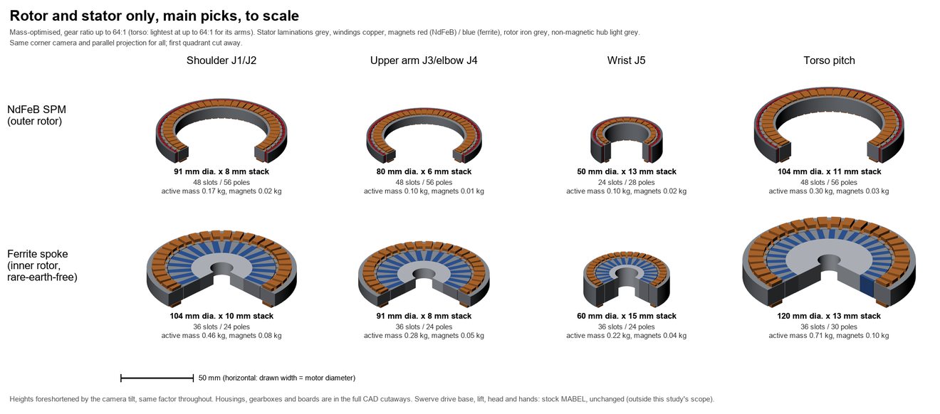
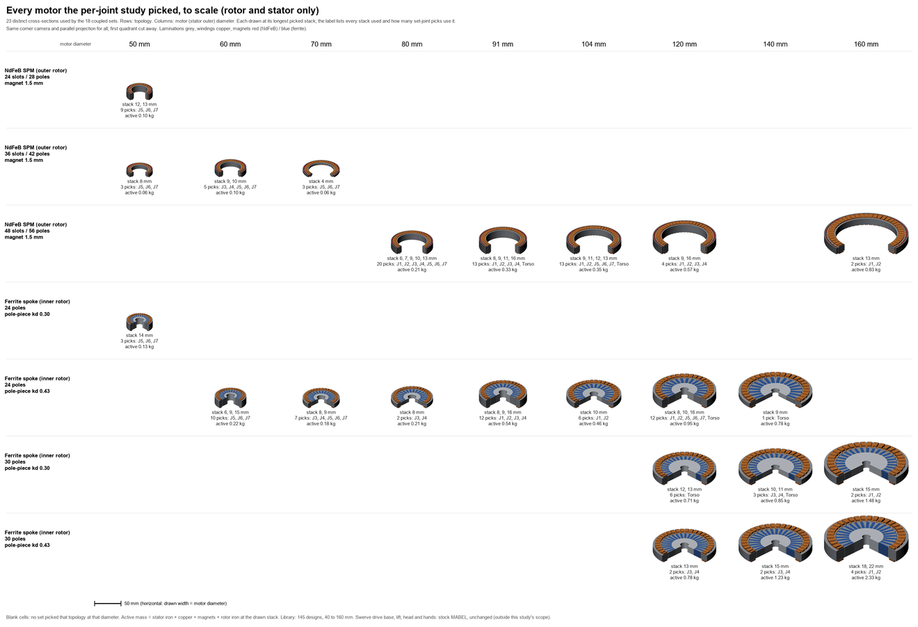
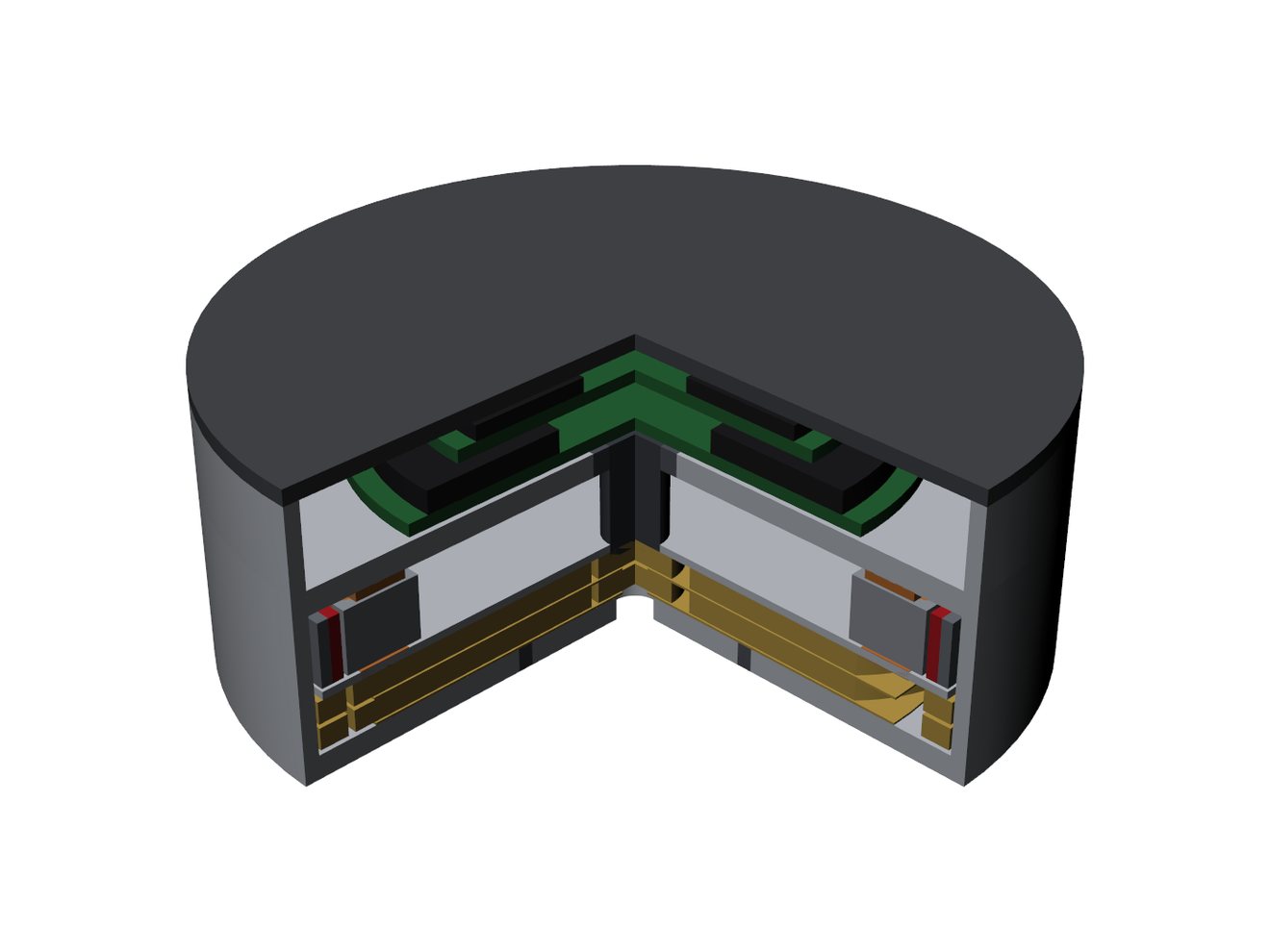
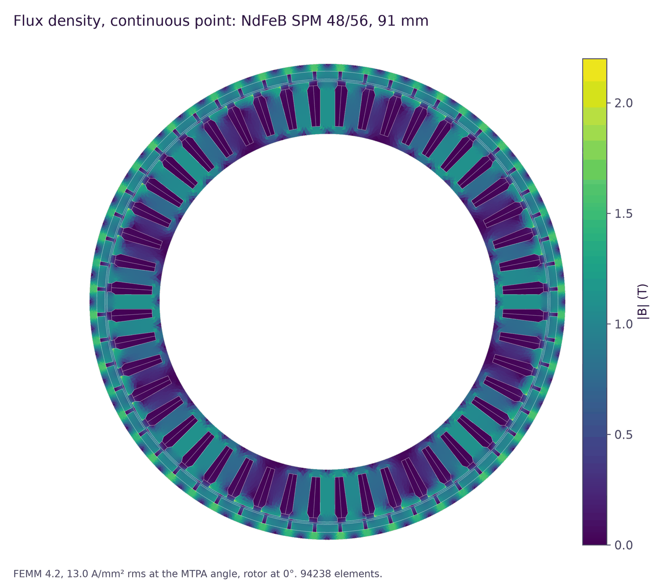
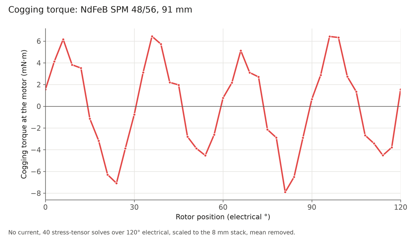
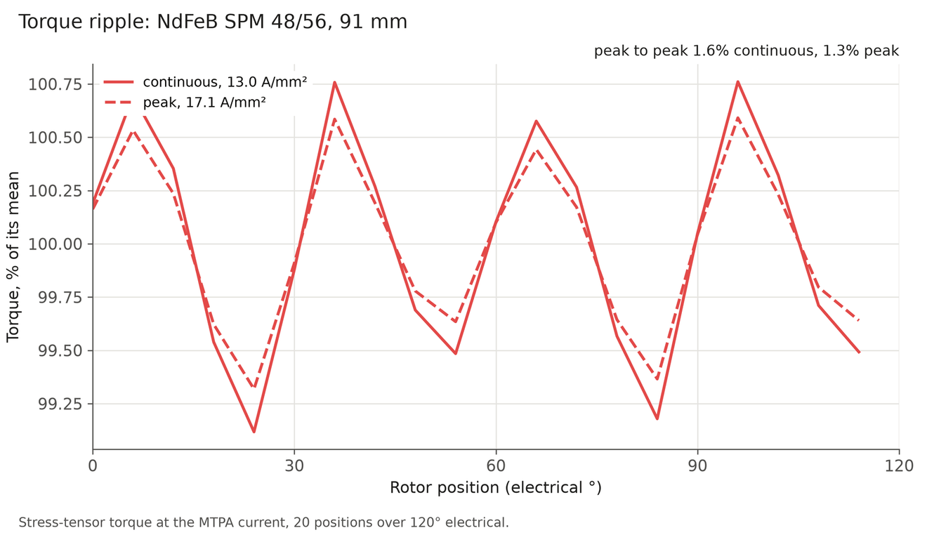
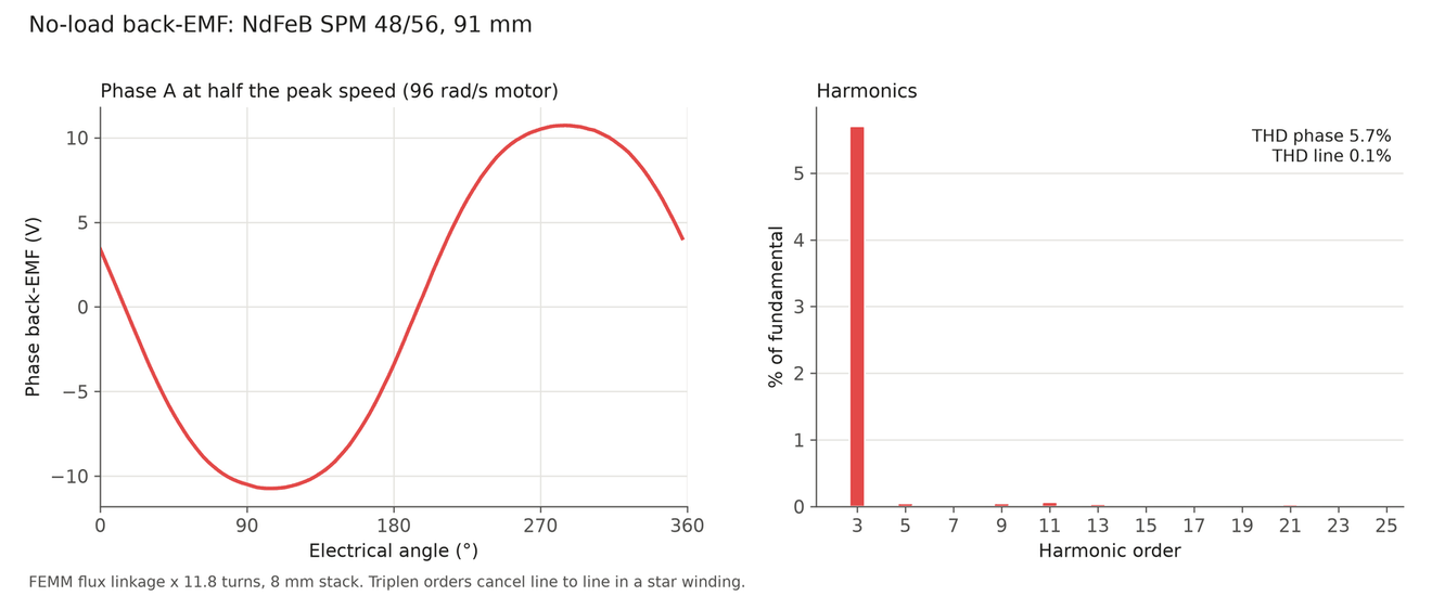
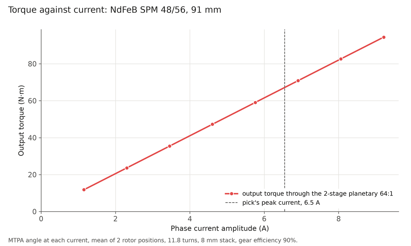
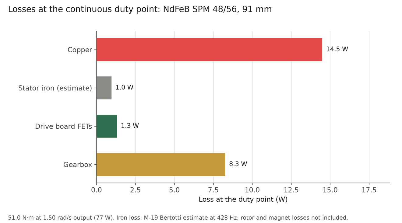
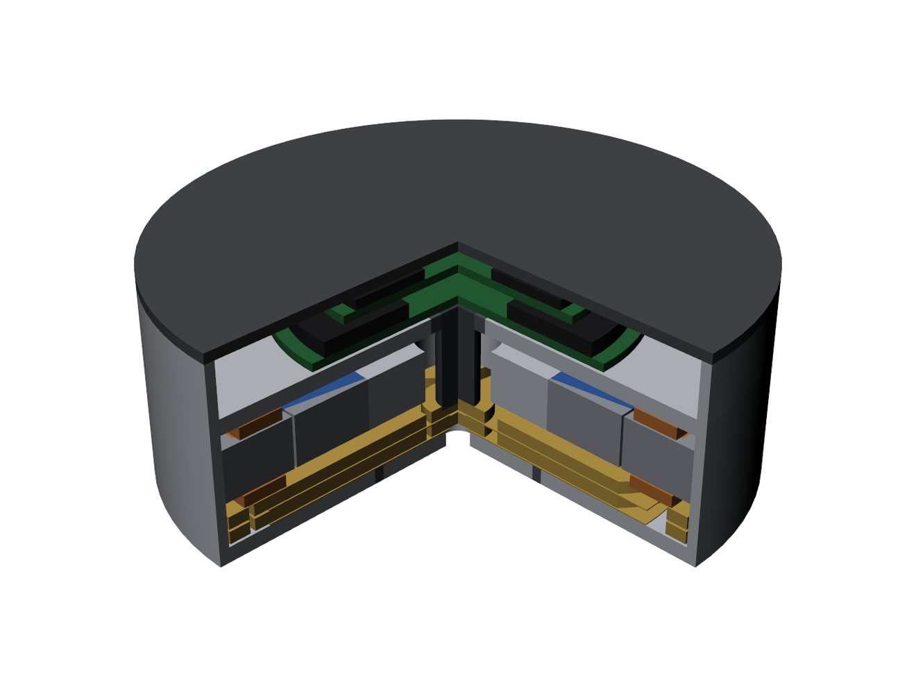
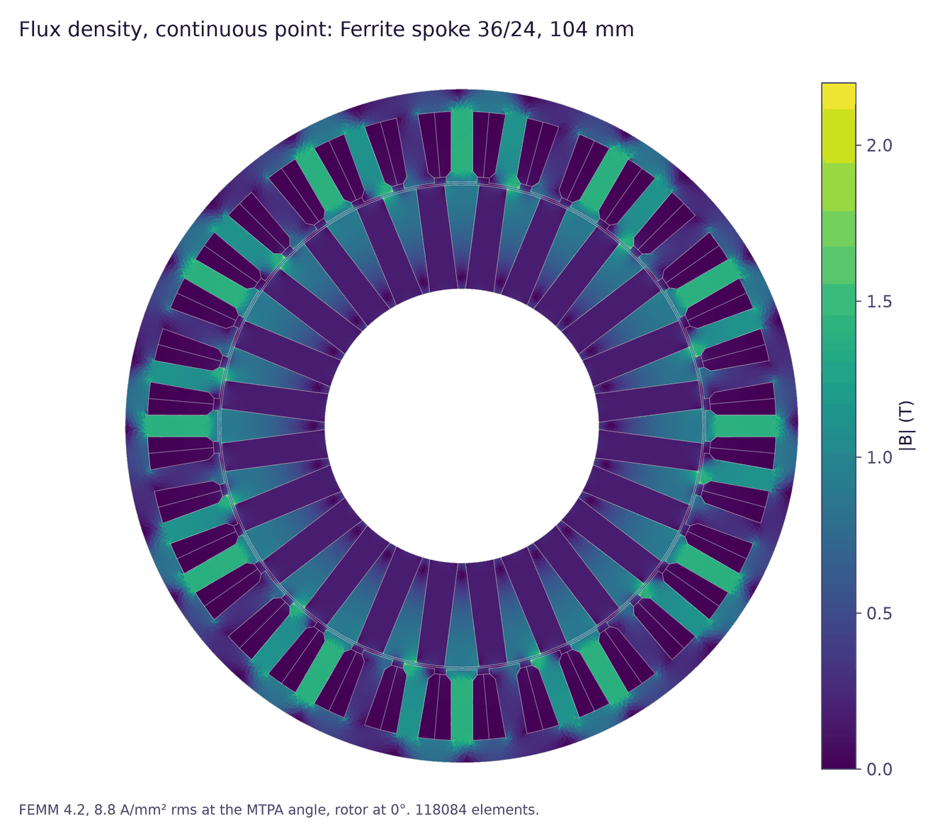
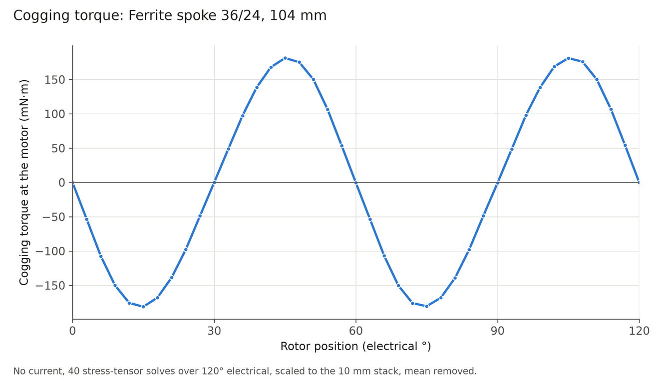
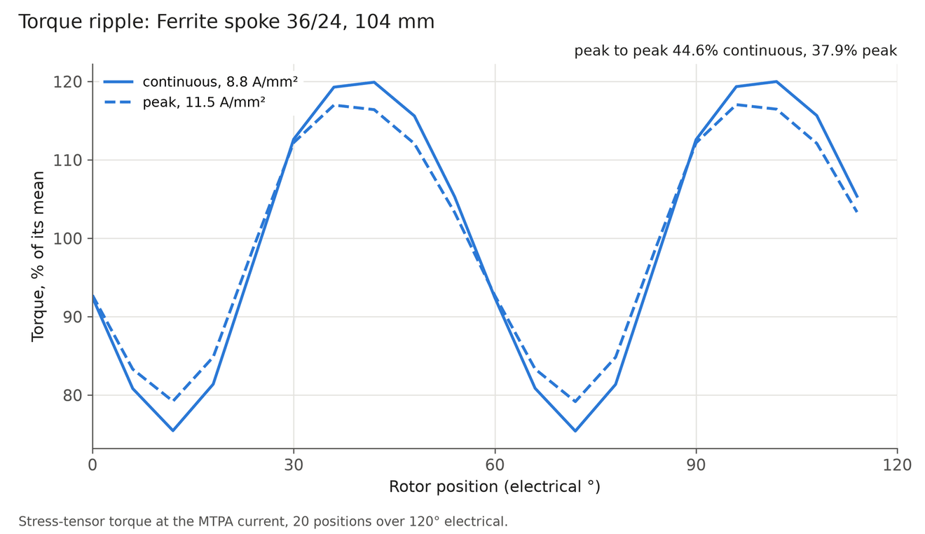
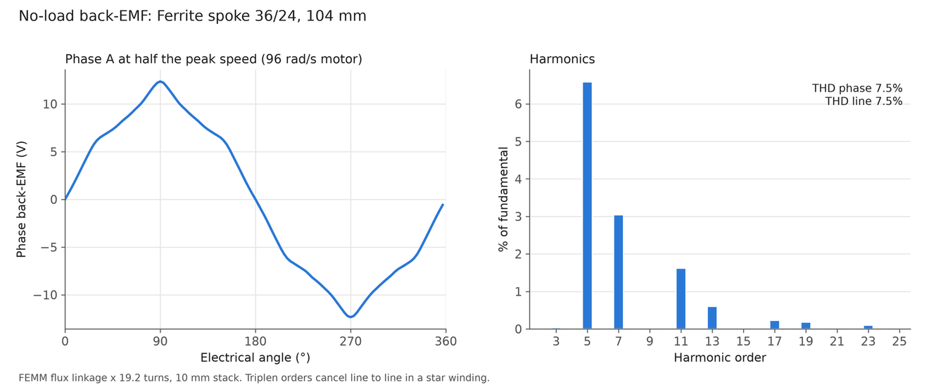
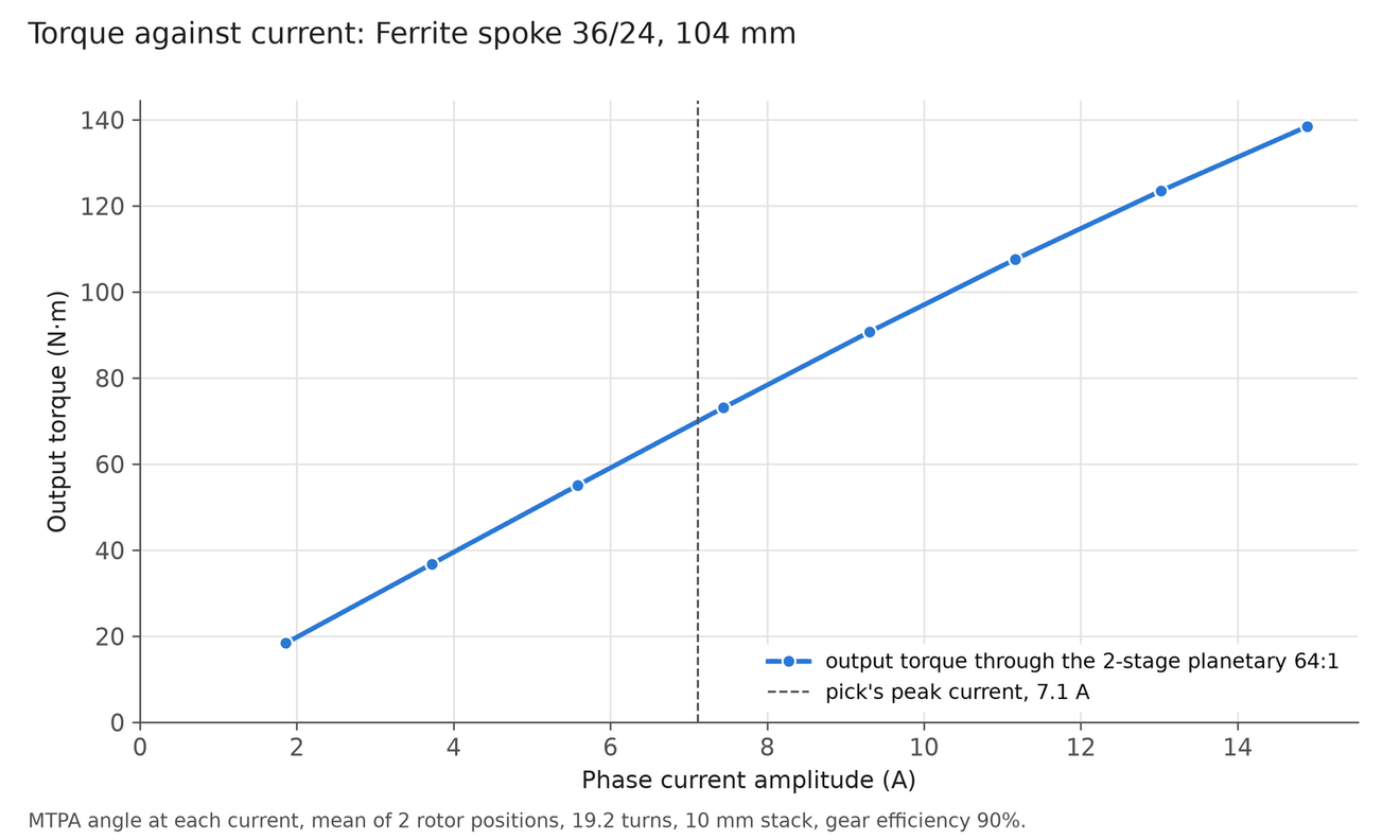
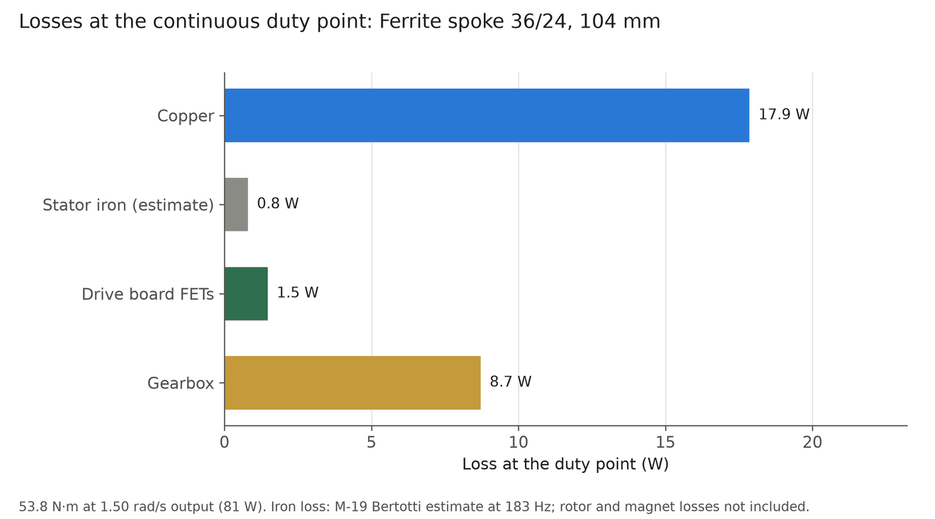
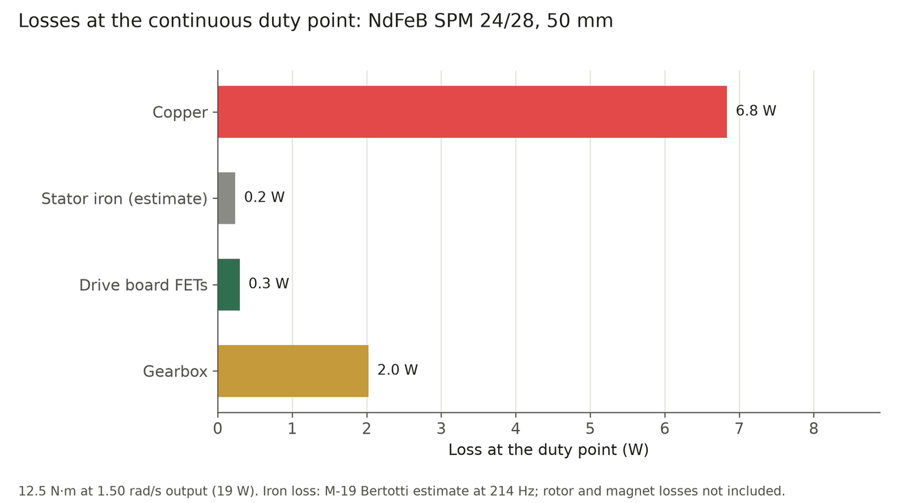
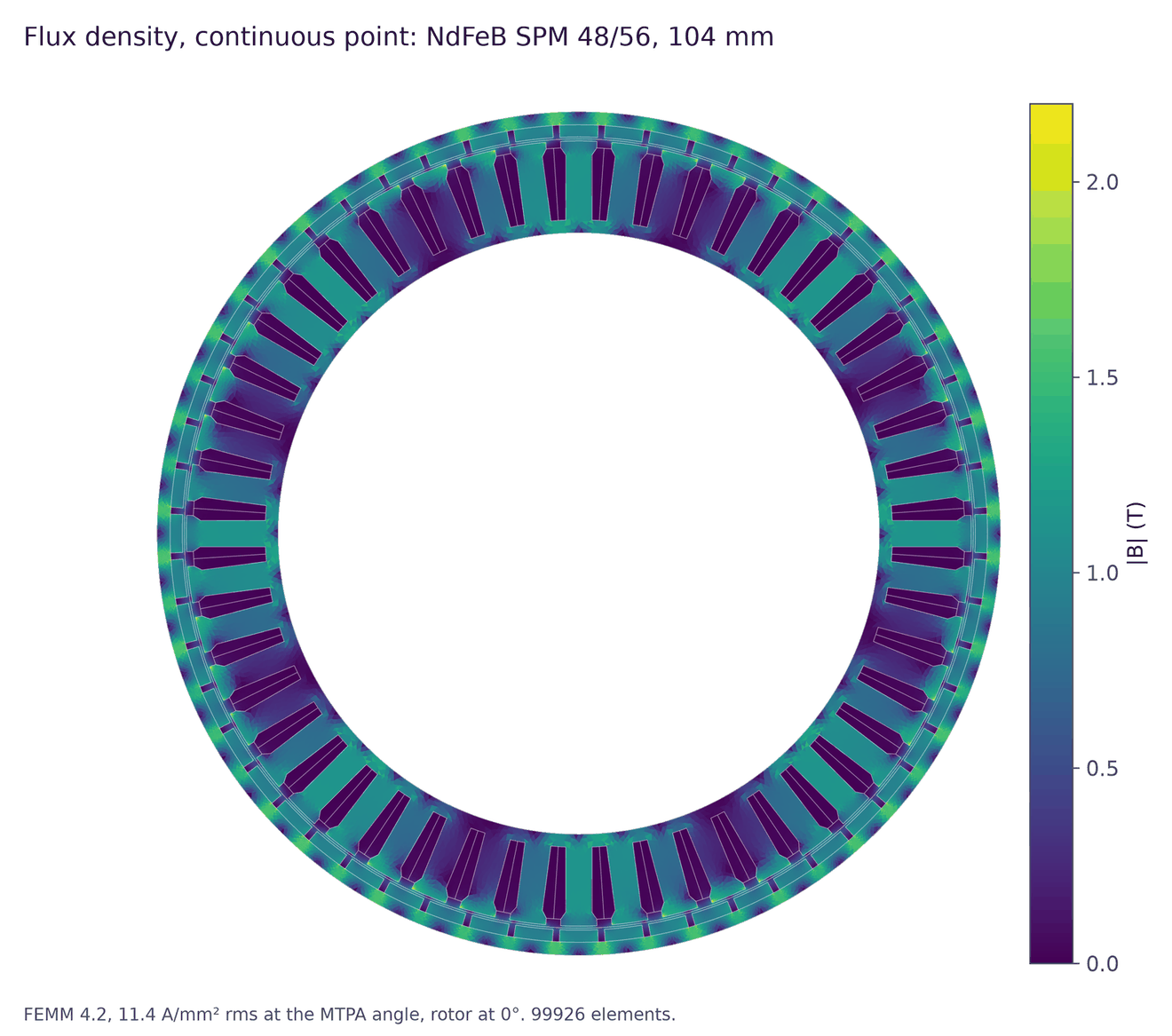
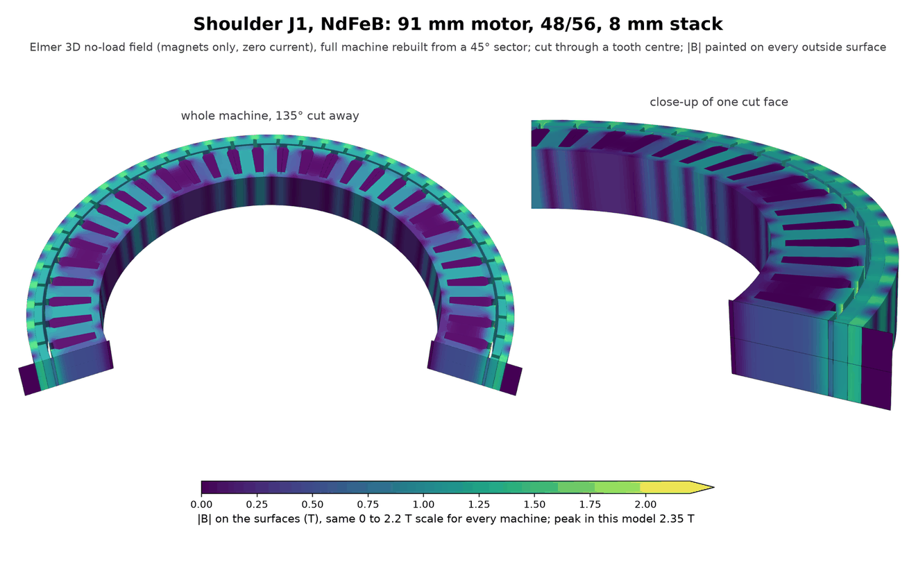
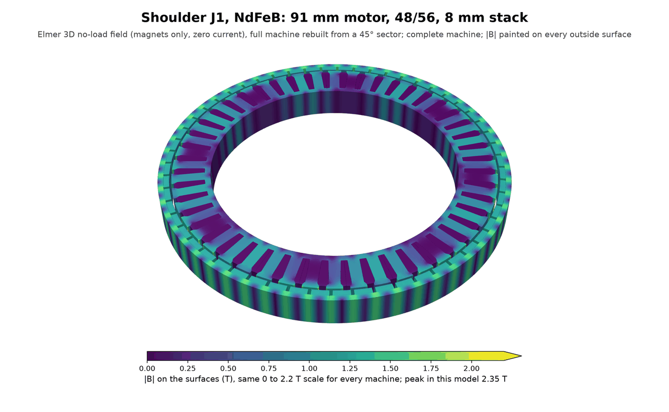
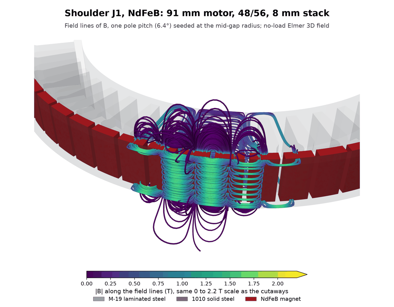
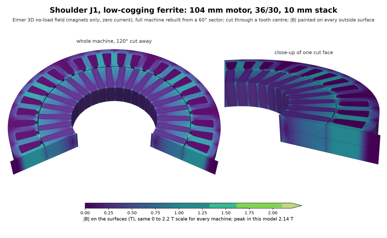
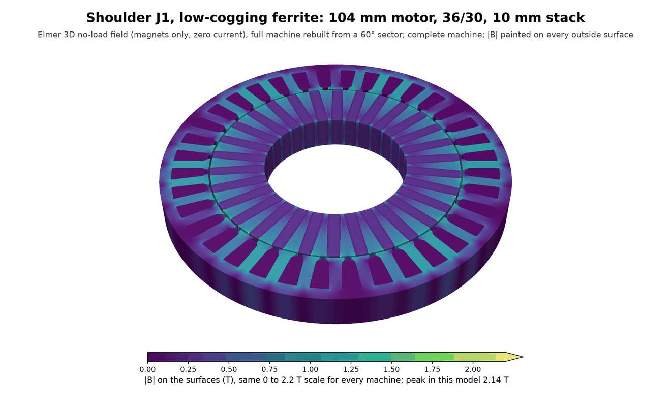
J1, and J2 with the same pick. NdFeB: 91 mm motor with an 8 mm stack, 48 slots and 56 poles, in a 97 × 36 mm actuator of 0.78 kg. Ferrite: 104 mm motor with a 10 mm stack, 36 slots and 24 poles in a spoke inner rotor, in a 108 × 40 mm actuator of 1.15 kg. The ferrite spoke has a cogging torque of 37.7% of its continuous torque and a torque ripple of 44.6%, against 1.6% for both in the NdFeB motor. Iron loss is a stator estimate.
Machines for the upper arm J3
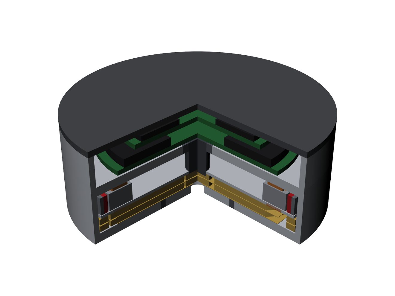
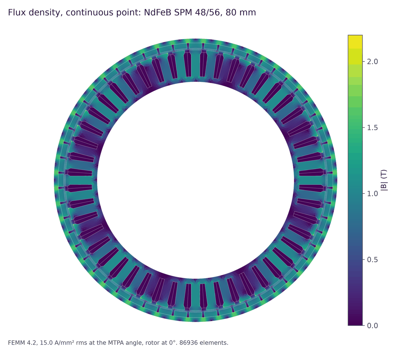
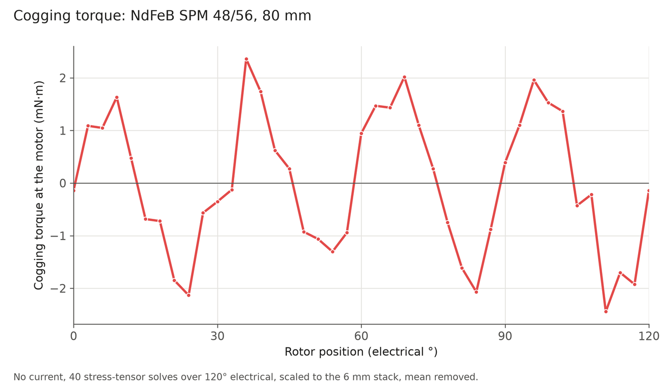
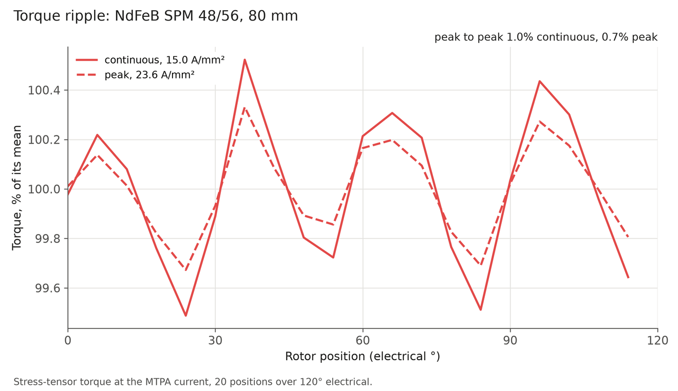
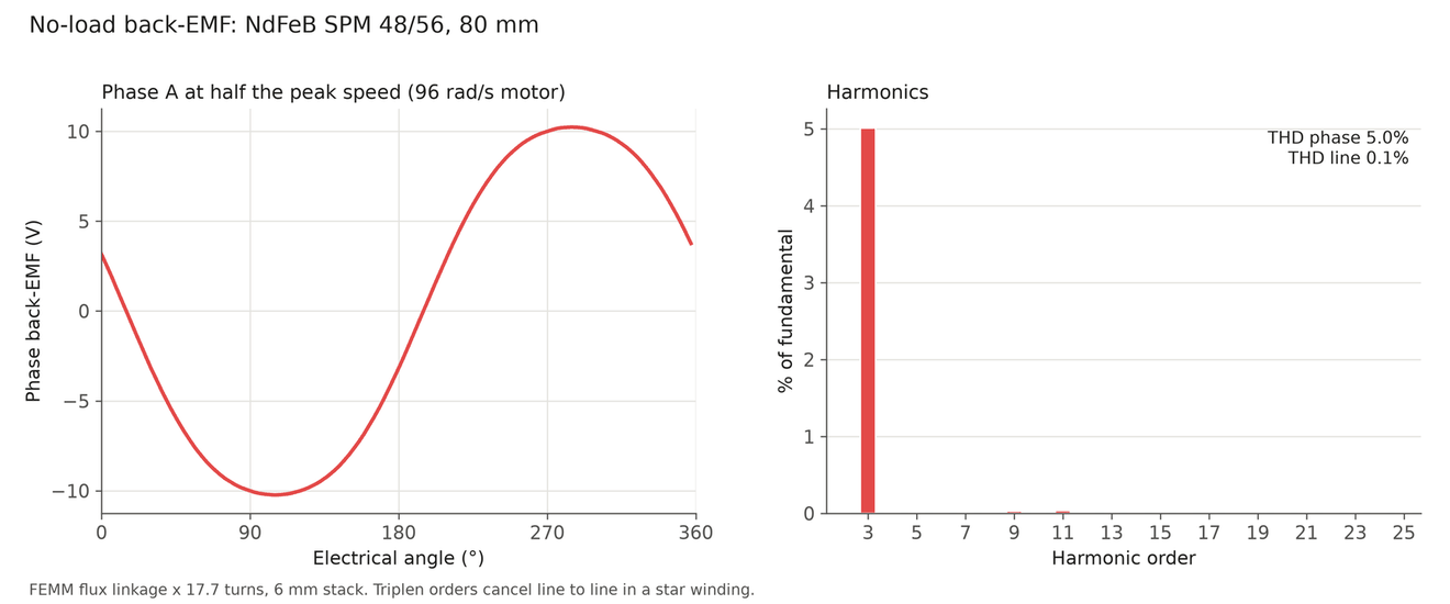
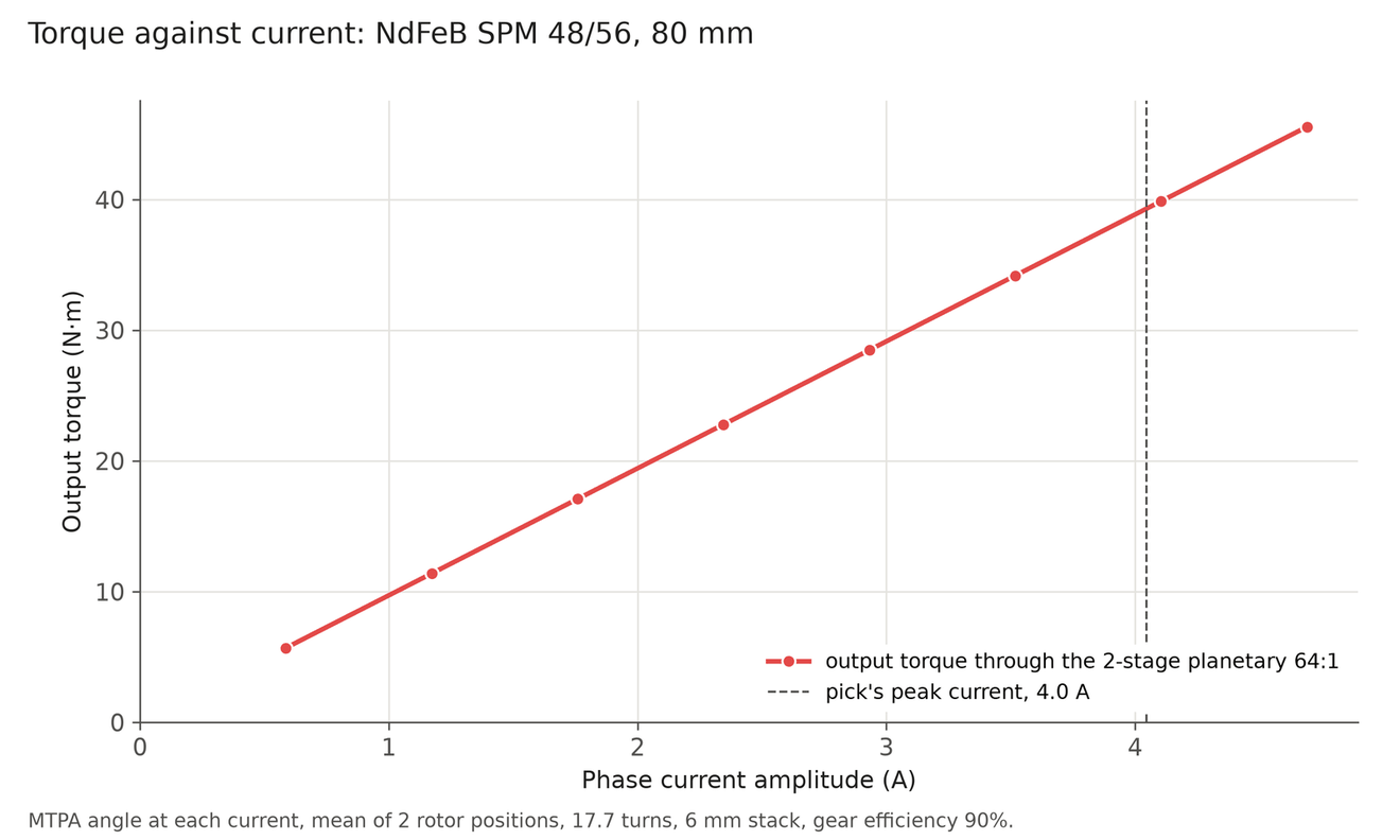
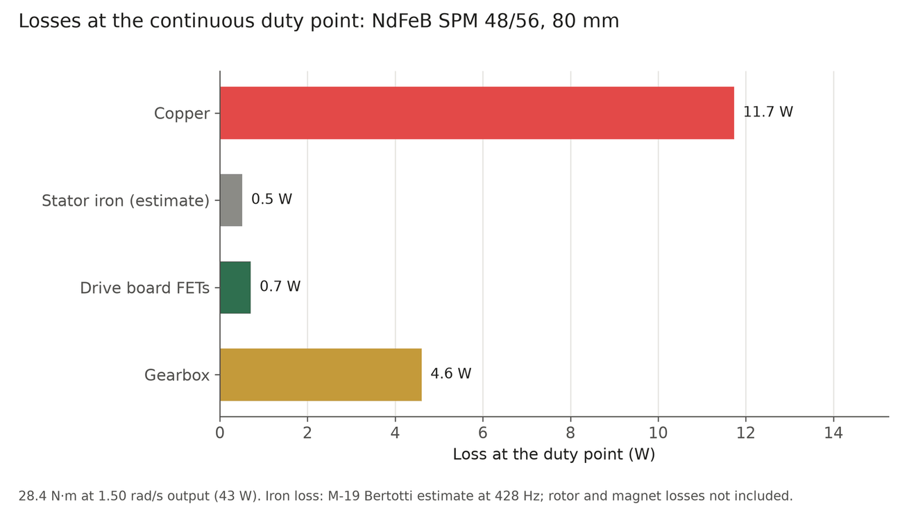
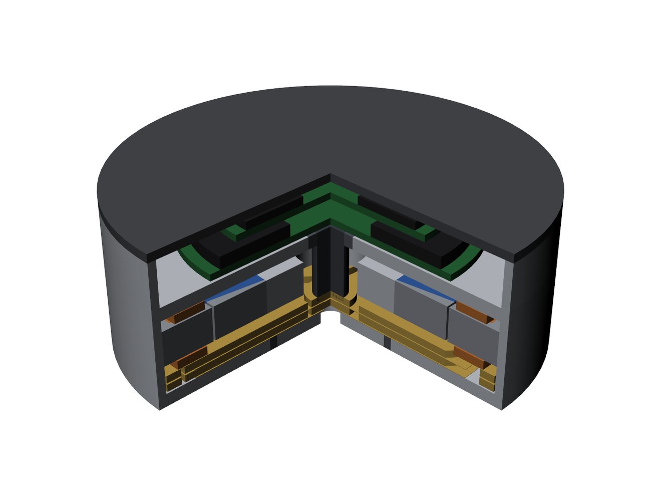
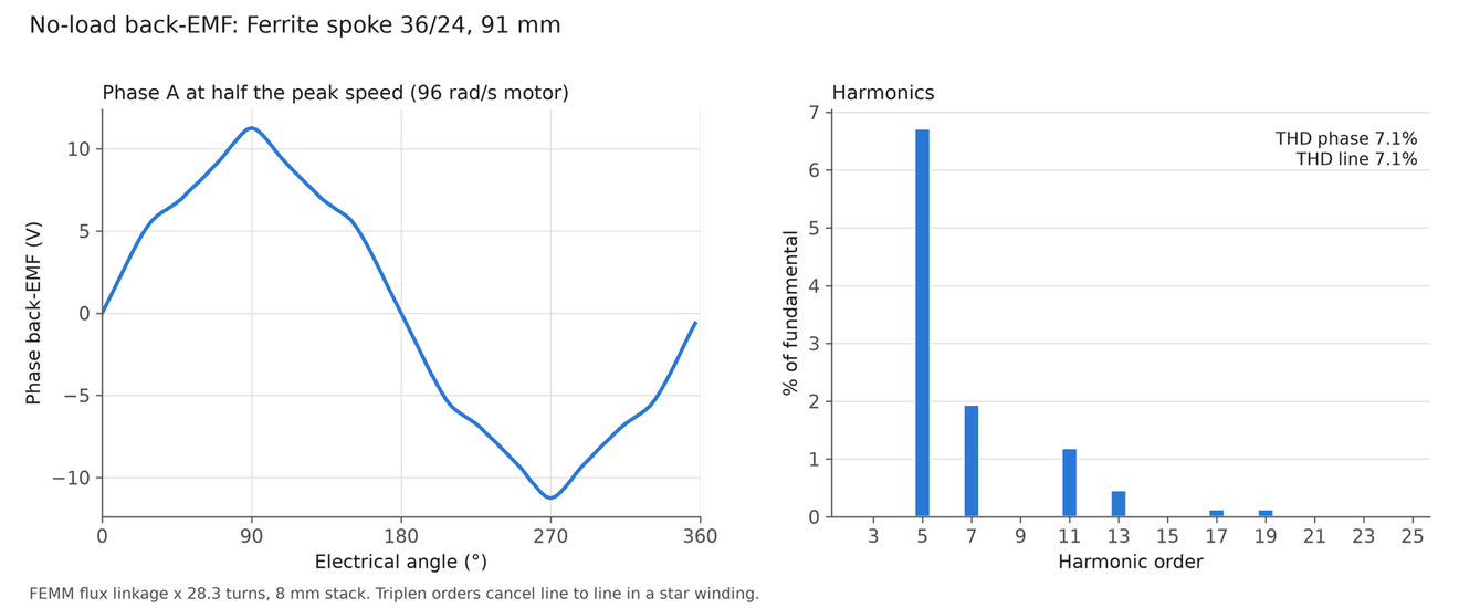
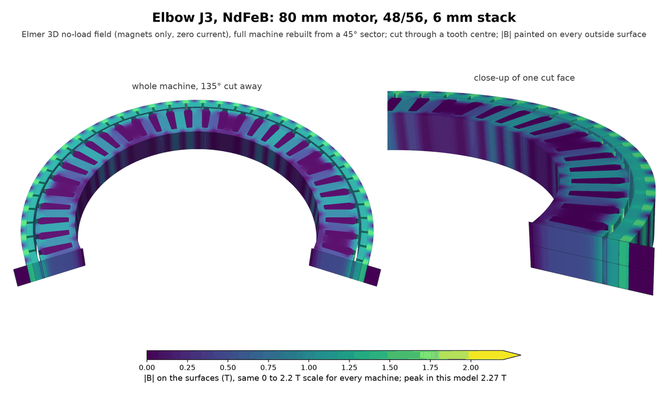
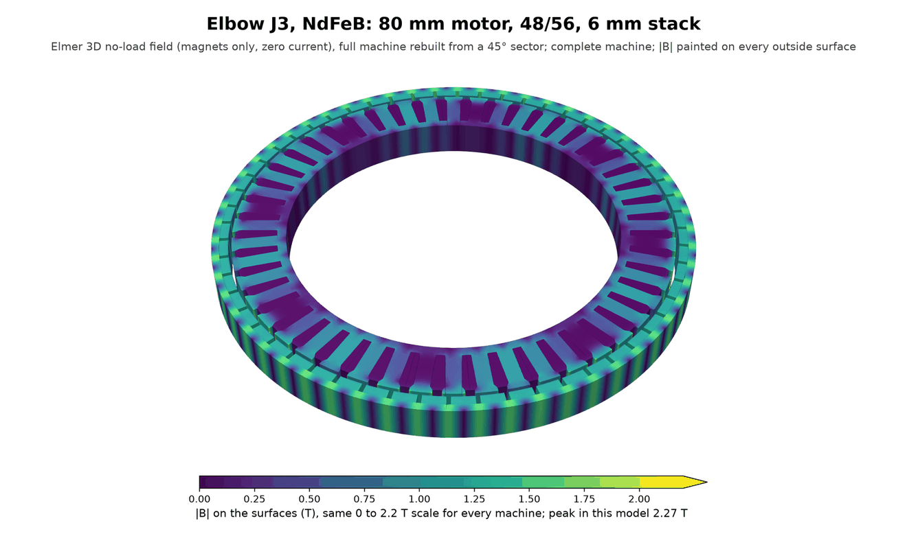
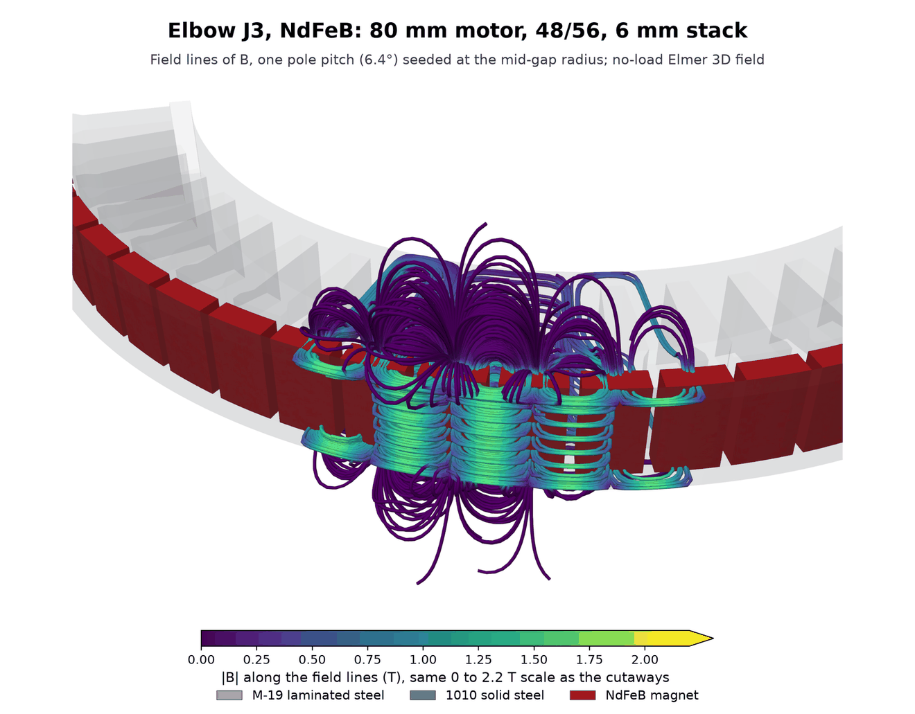
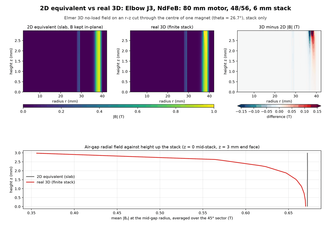
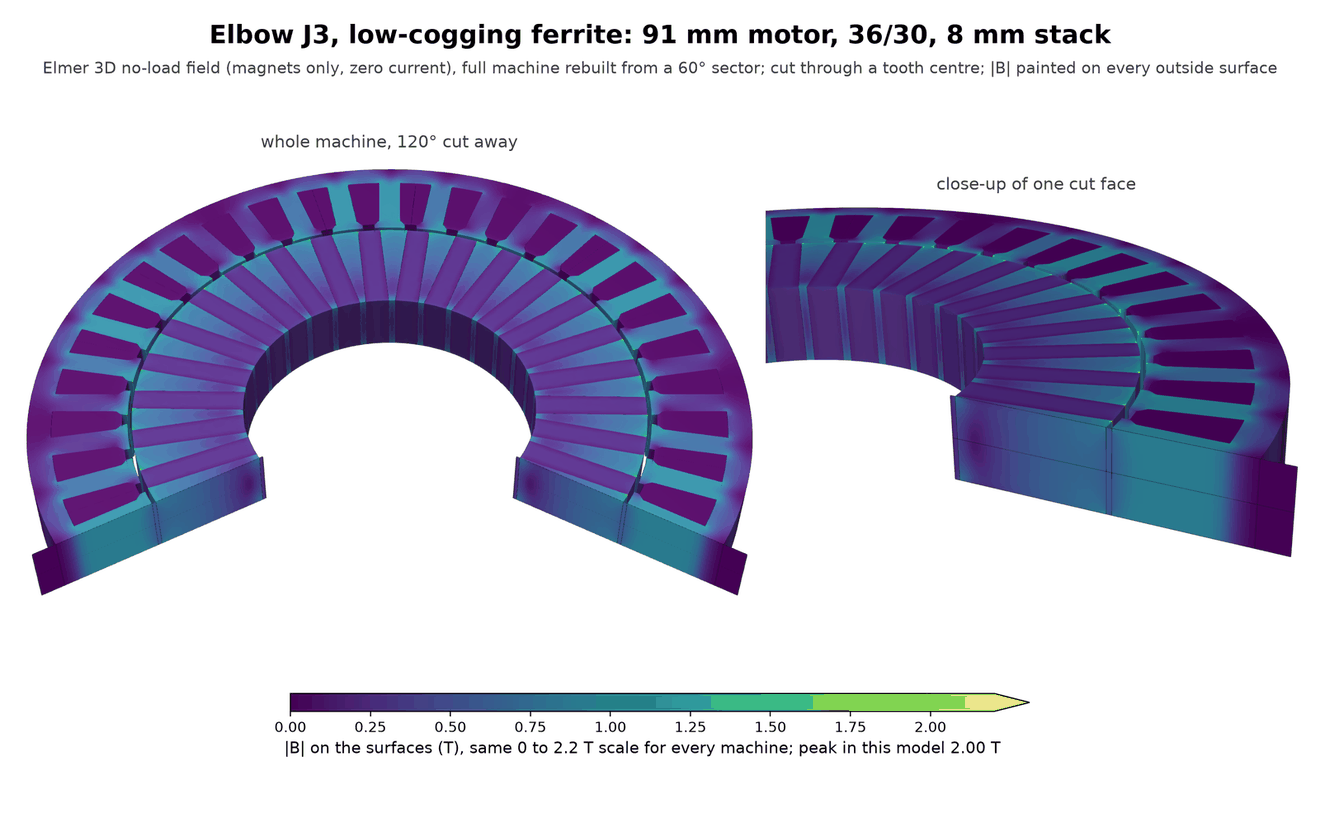
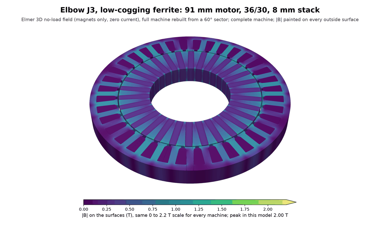
J3, and J4 with the same pick. NdFeB: 80 mm motor with a 6 mm stack, 48 slots and 56 poles, in an 86 × 32 mm actuator of 0.55 kg. Ferrite: 91 mm motor with an 8 mm stack, 36 slots and 24 poles, in a 95 × 35 mm actuator of 0.79 kg.
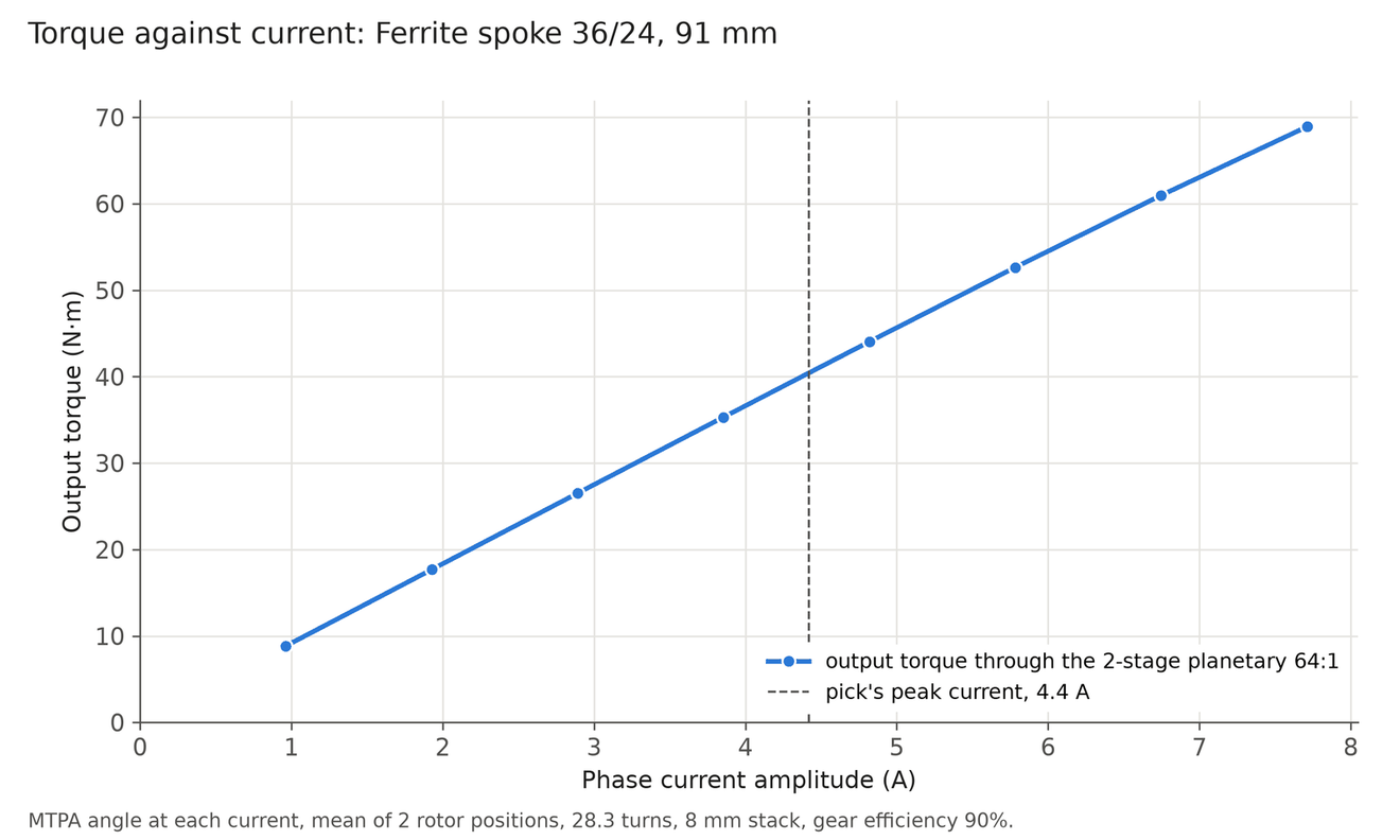
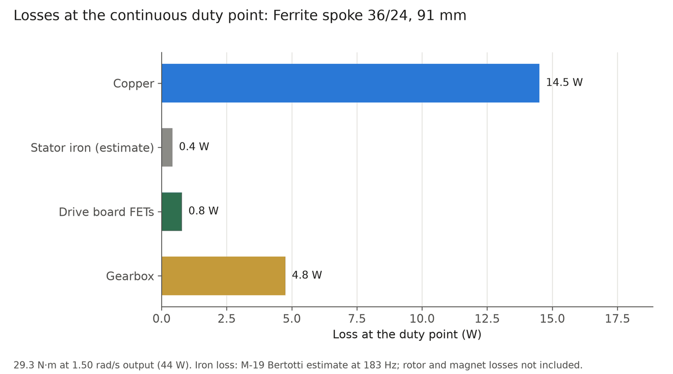
Machines for the wrist J5
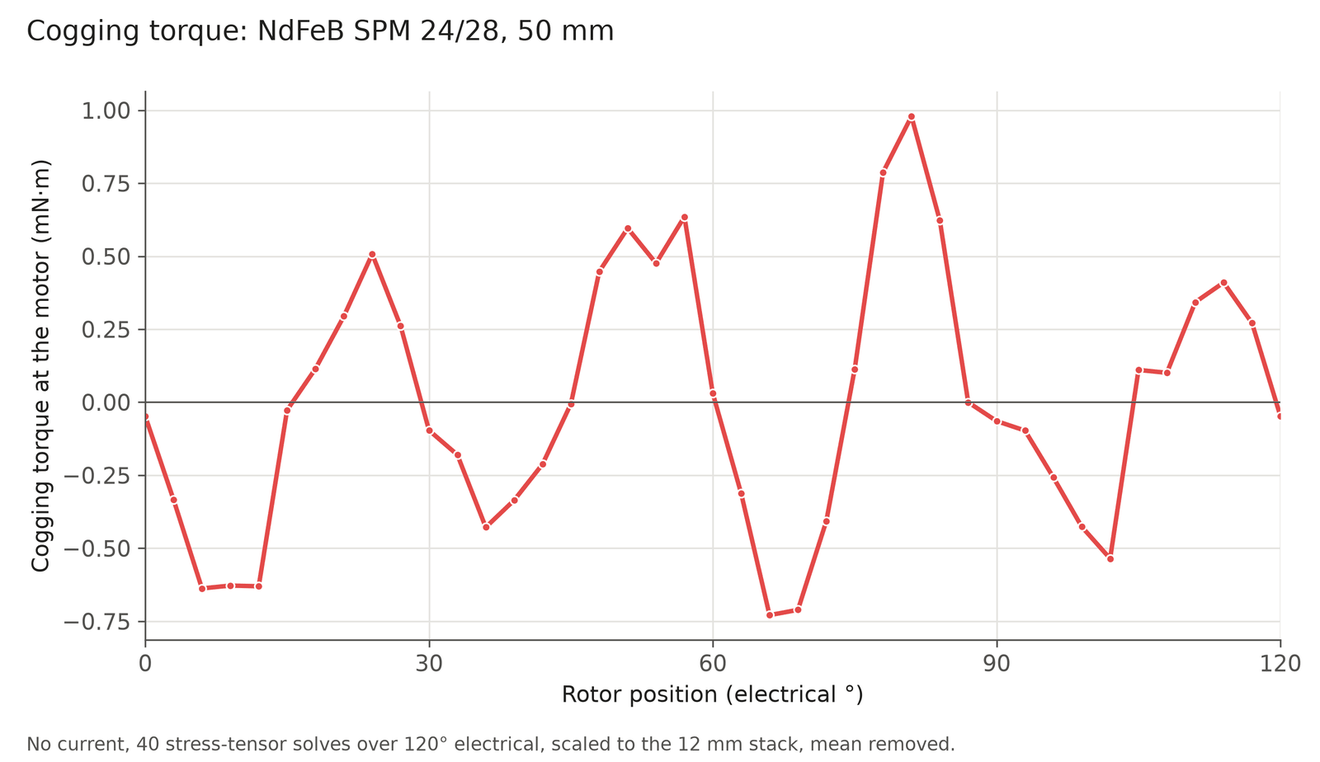
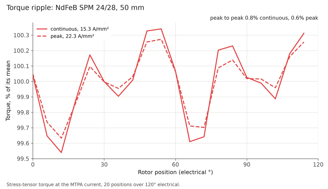
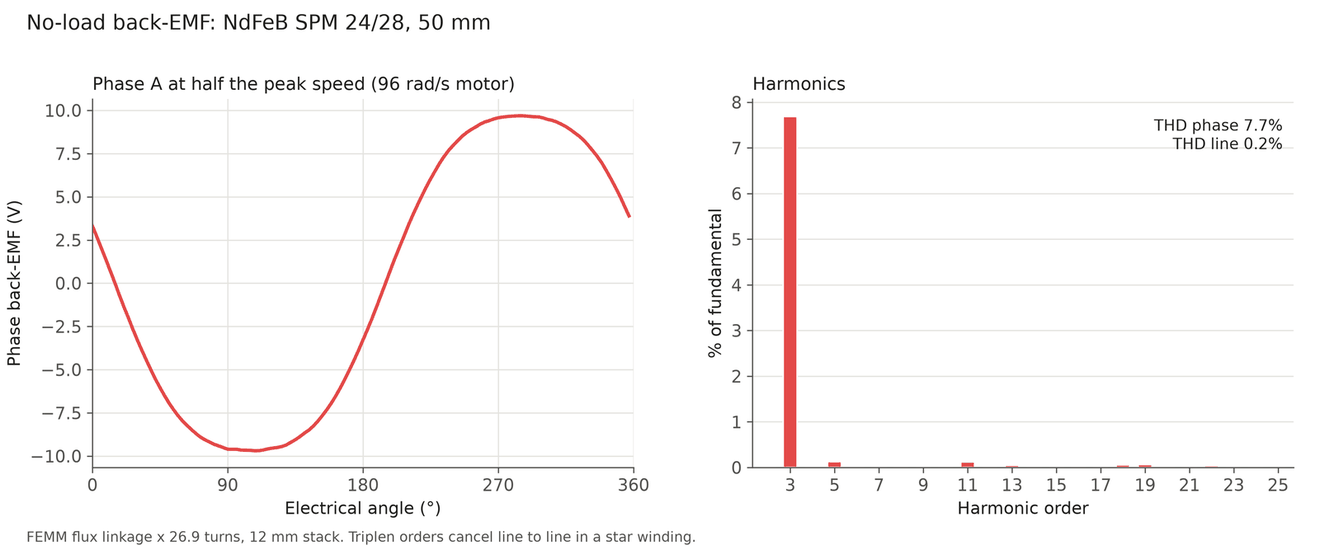
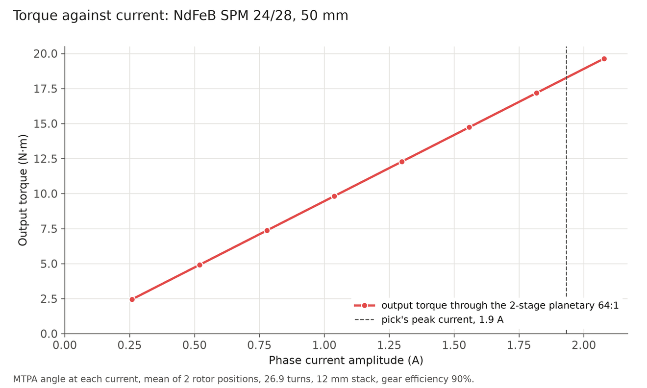
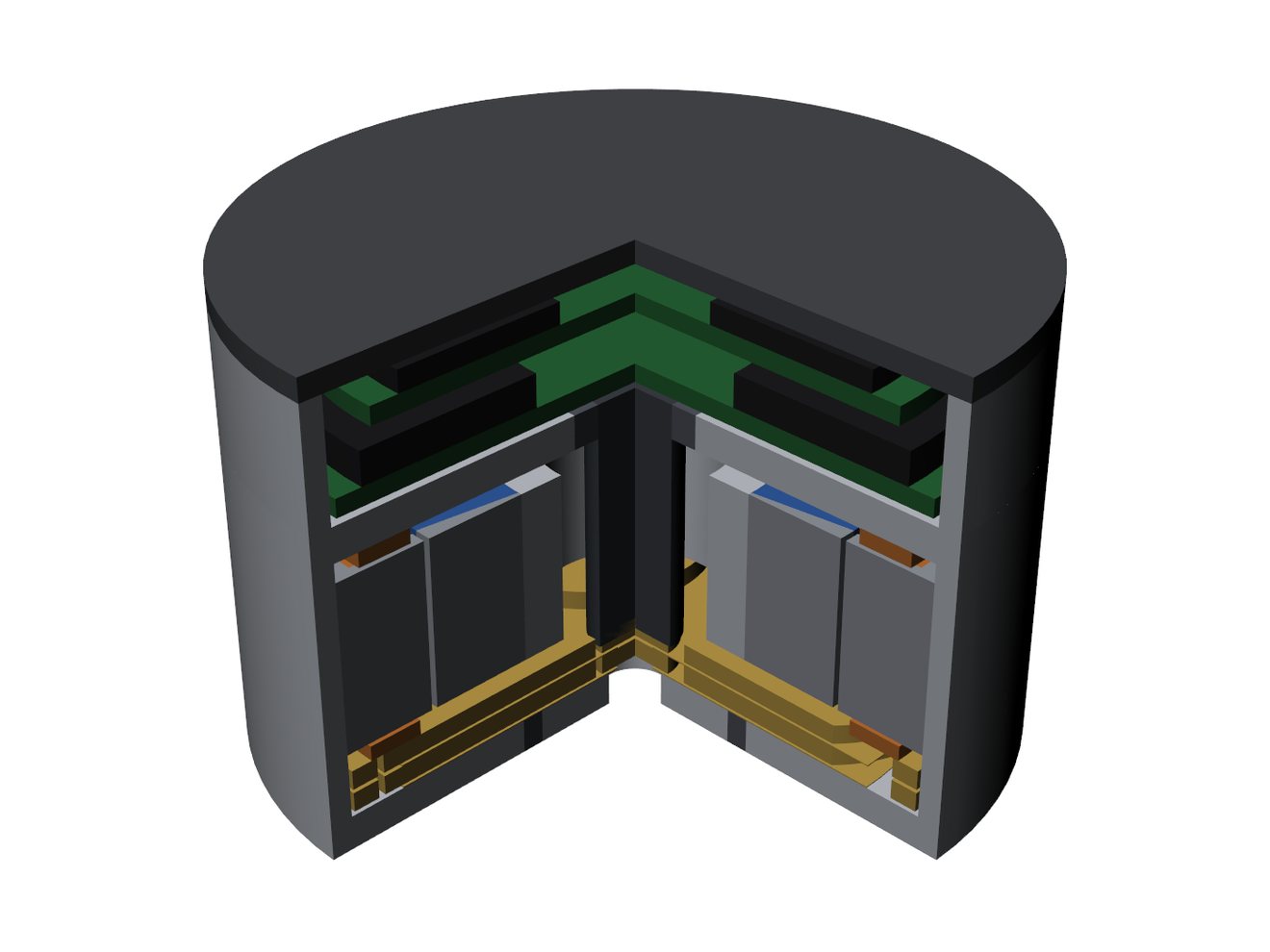
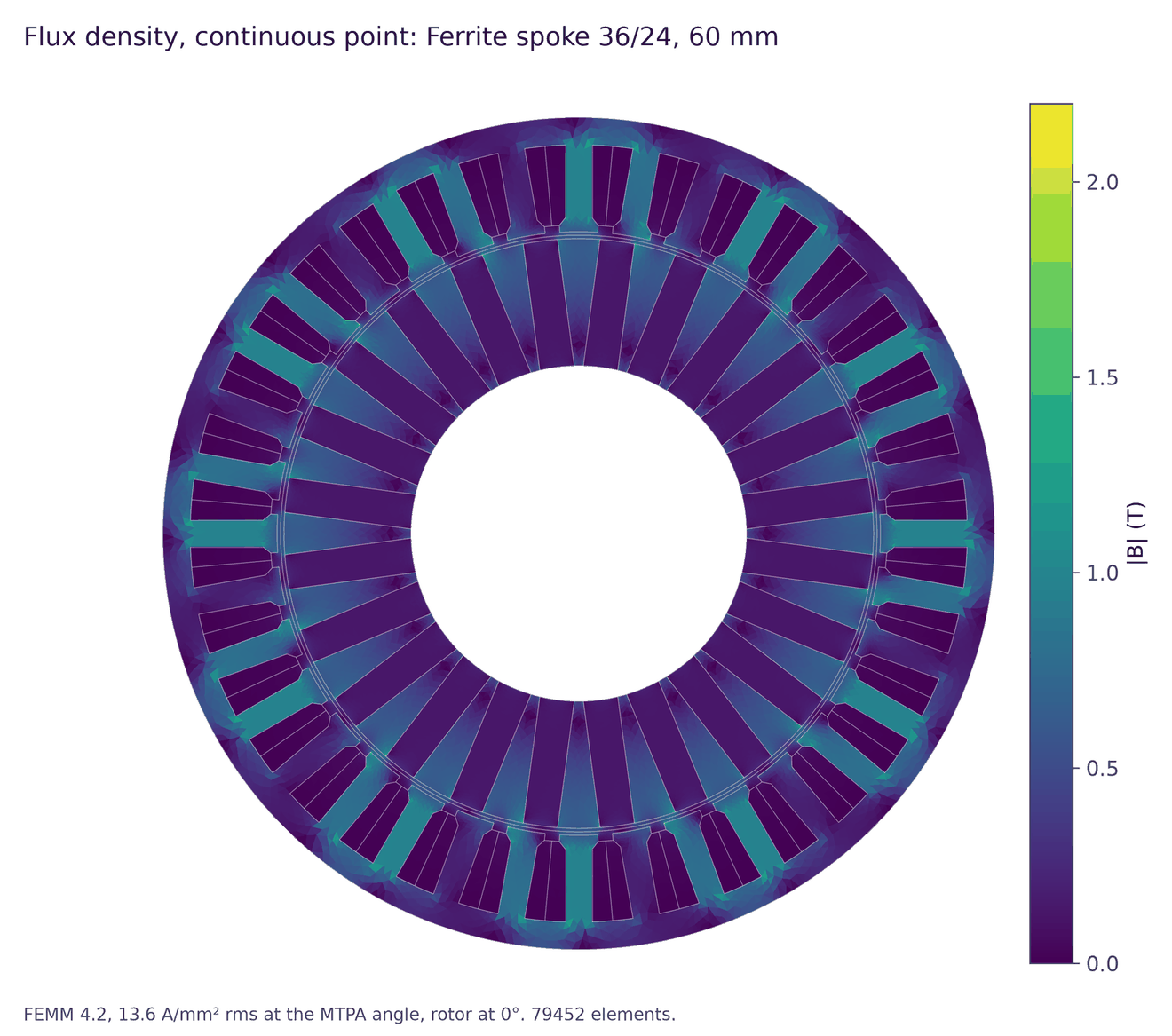
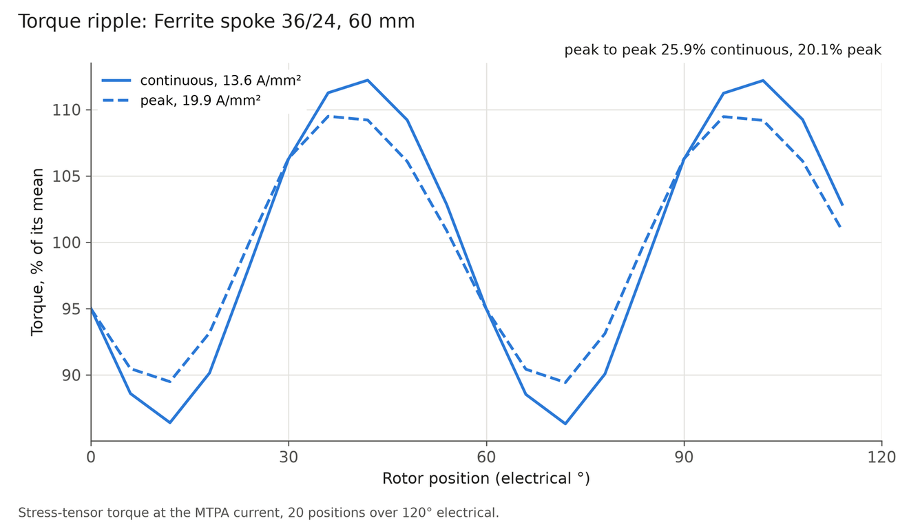
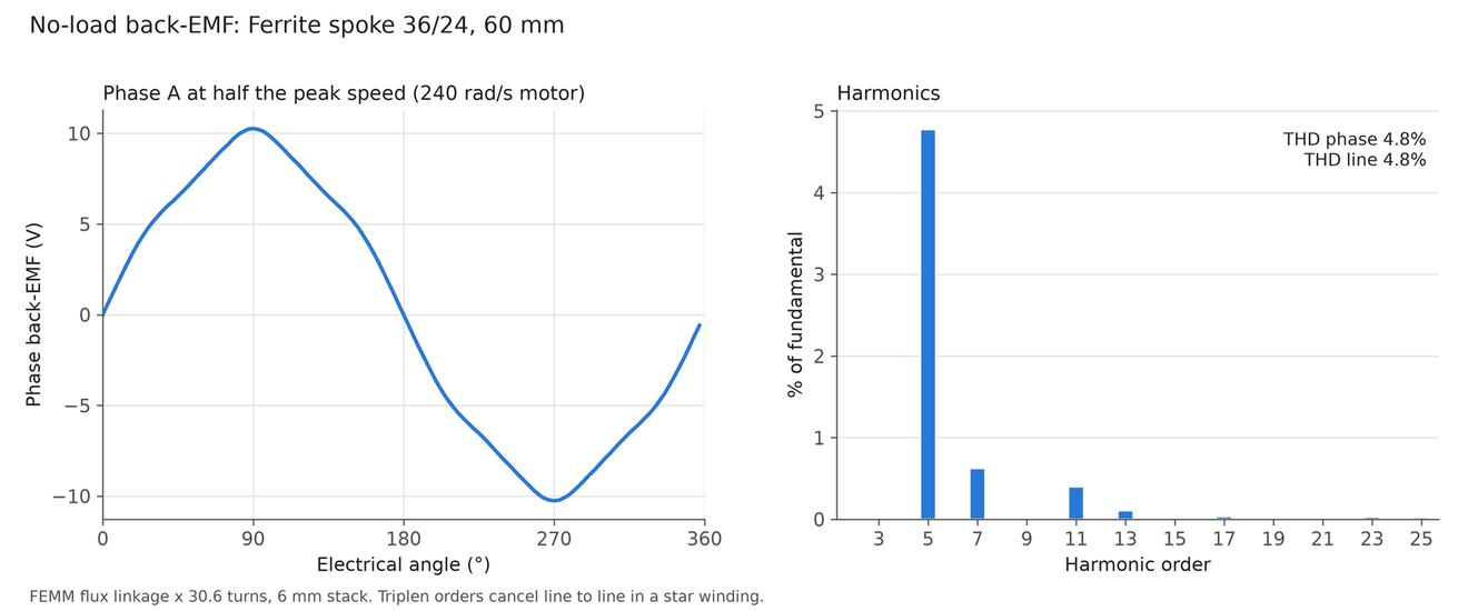
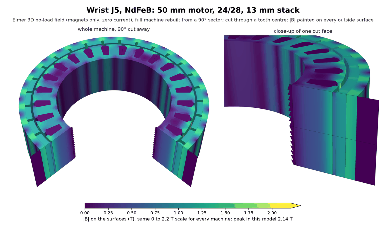
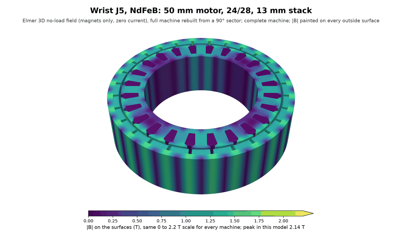
J5. NdFeB: 50 mm motor, 24 slots and 28 poles, in a 56 × 40 mm actuator of 0.35 kg with a 13 mm stack. Ferrite: 60 mm motor, 36 slots and 24 poles, in a 64 × 41 mm actuator of 0.51 kg with a 15 mm stack. These charts are for the motor cross-section at one stack length, 12 mm for NdFeB and 6 mm for ferrite, which differ from the stacks of the picks. The flux map, torque ripple and back-EMF shapes hardly depend on the stack. The cogging torque is scaled to the drawn stack. The torque-current and loss charts of the ferrite wrist motor are left out, because they were drawn for a different gearbox and stack than the pick.
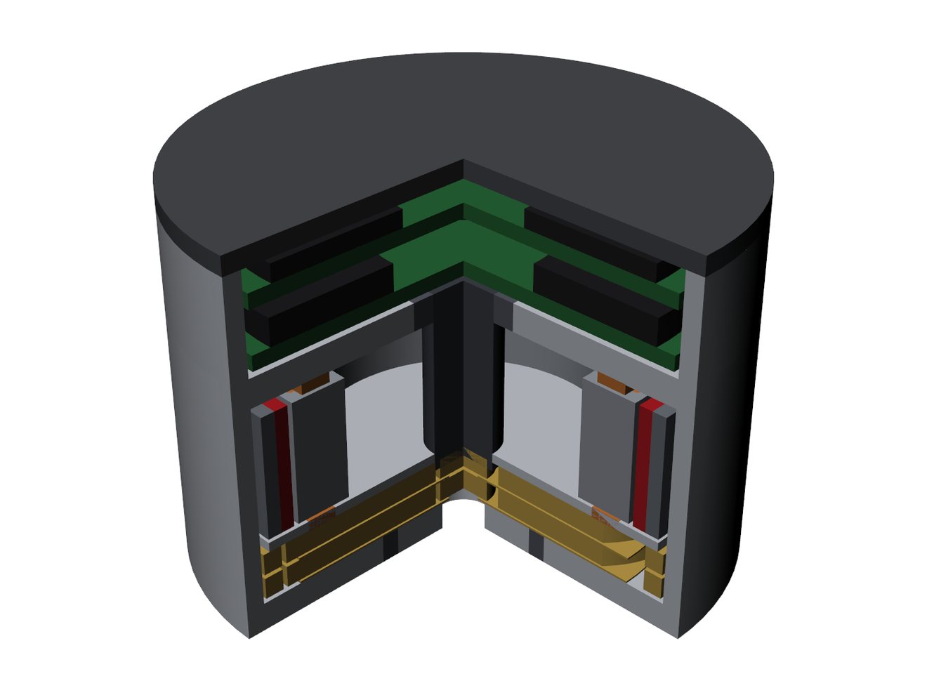
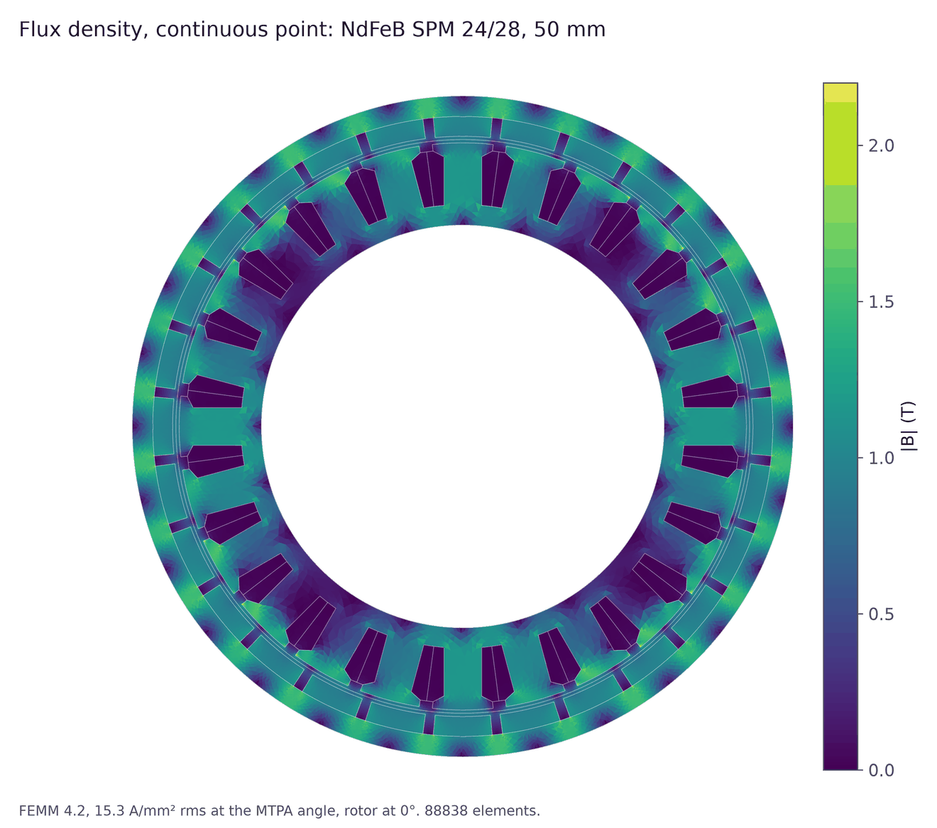
Machines for the torso pitch
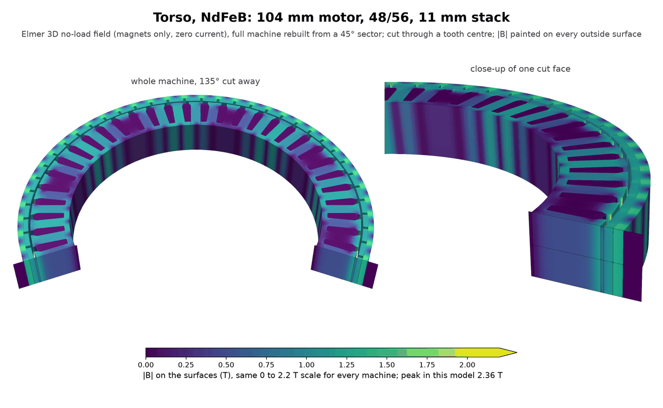
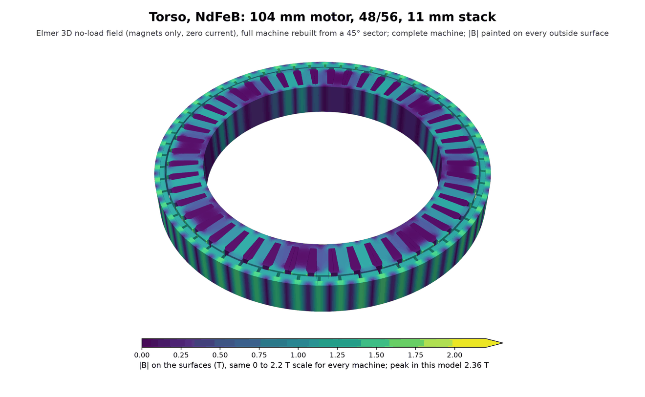
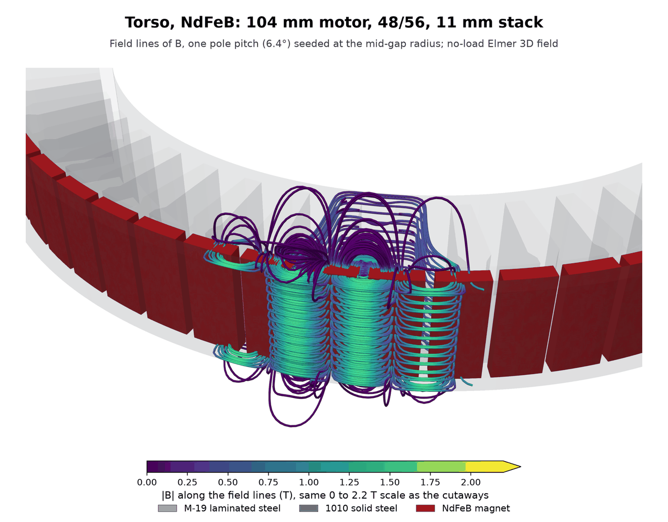
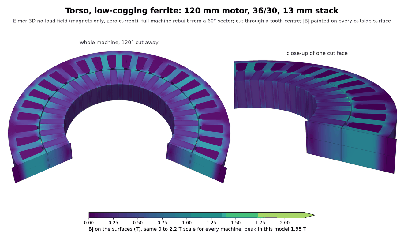
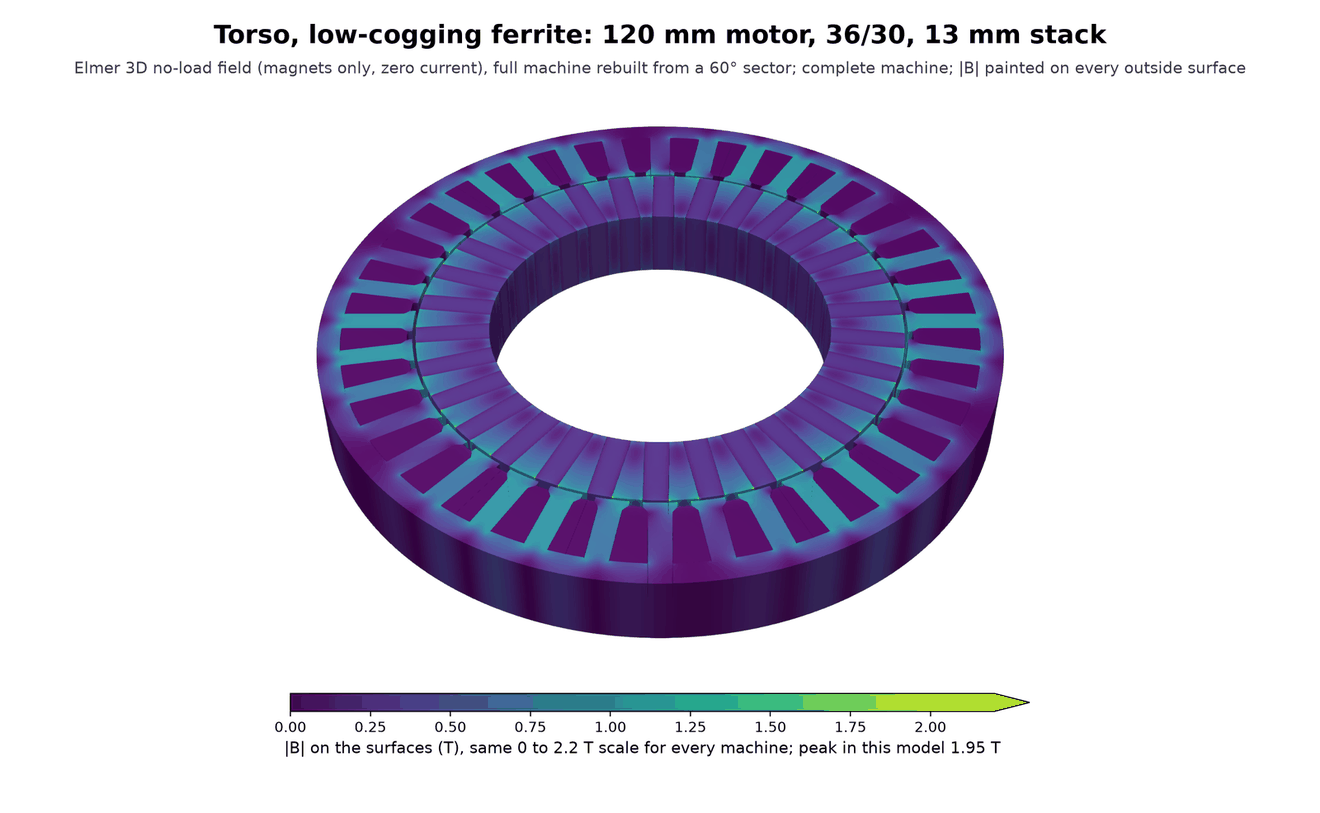
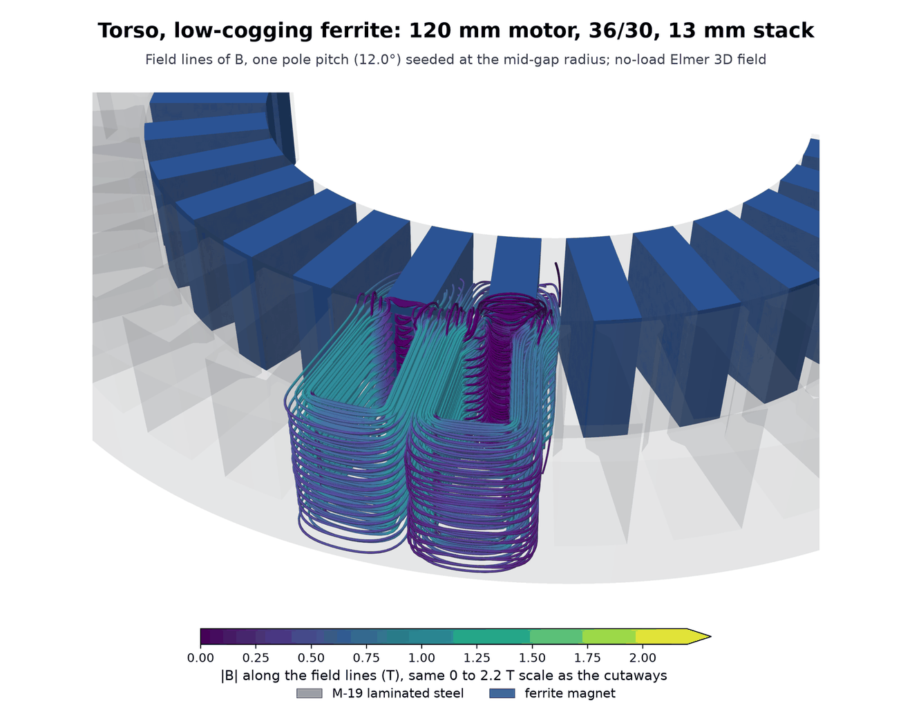
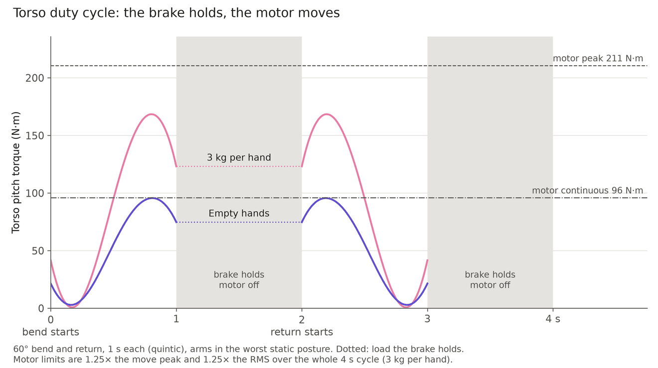
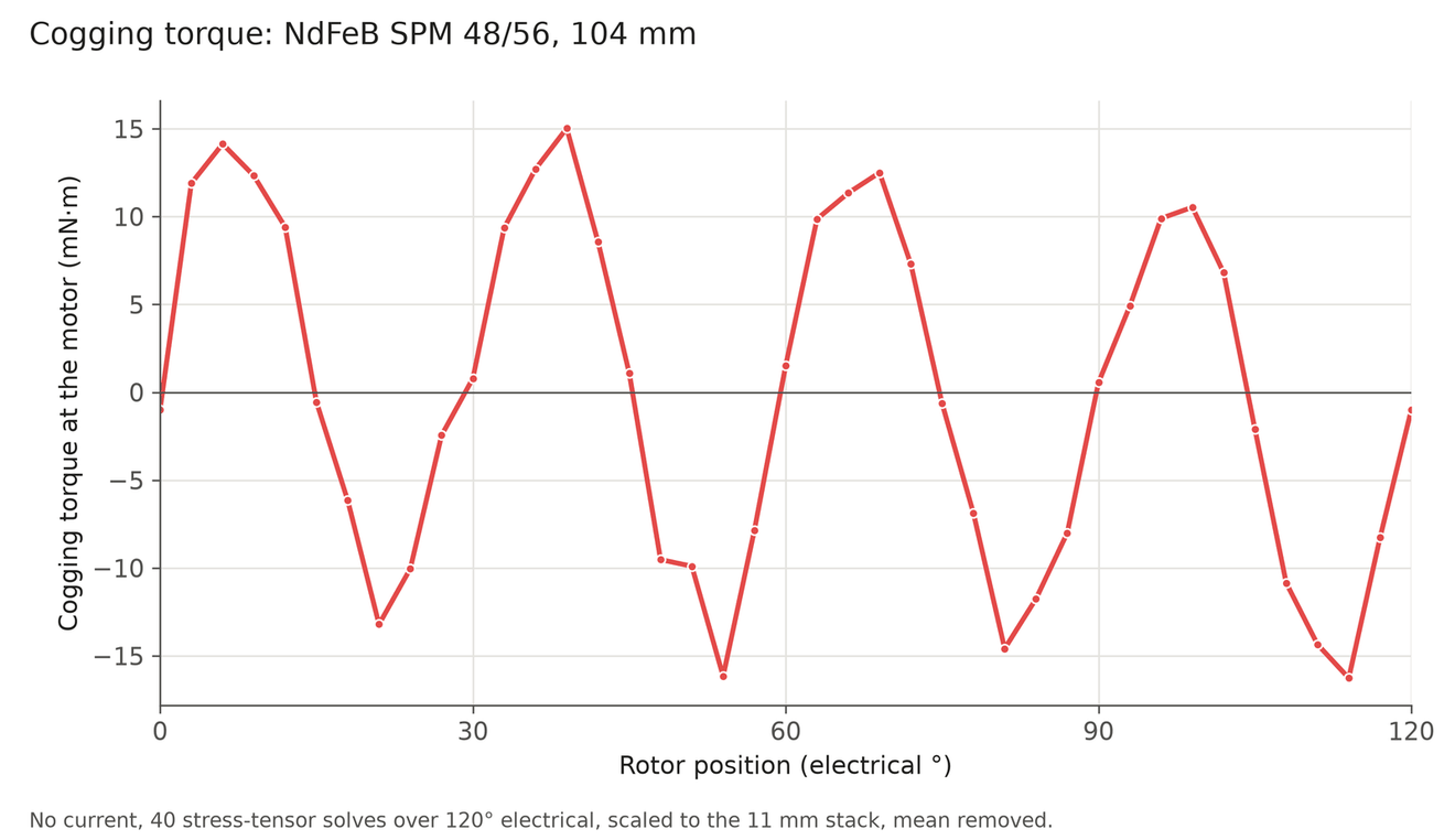
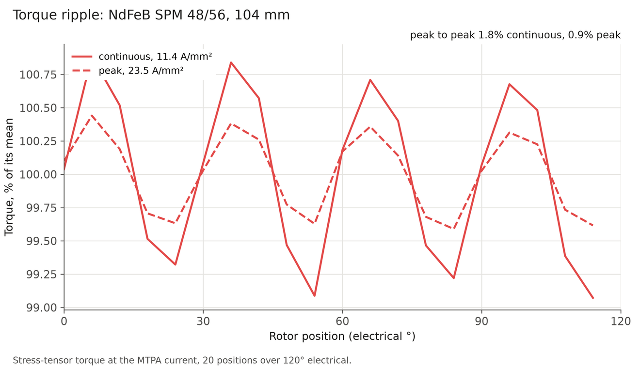
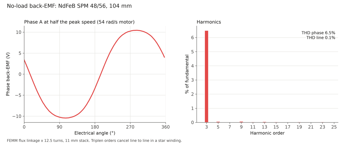
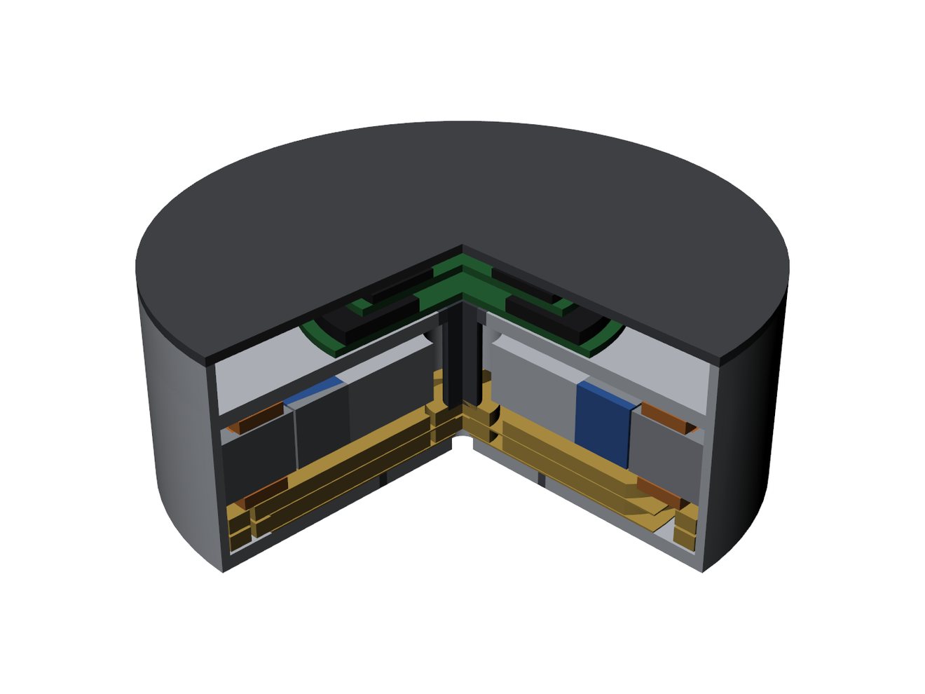
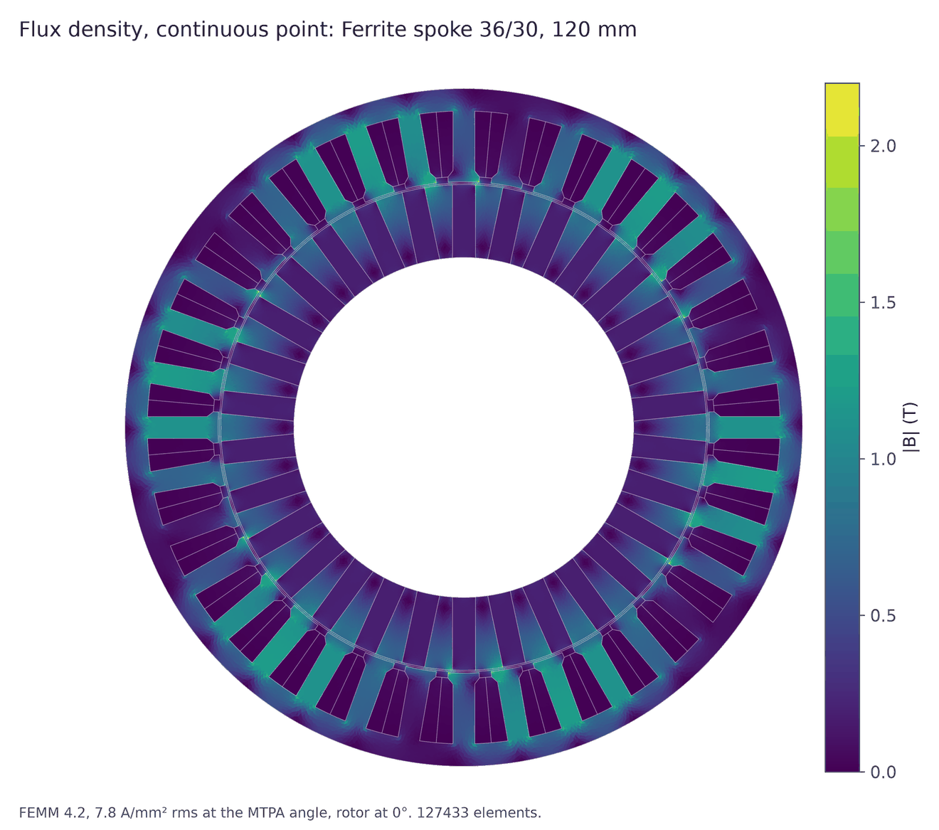
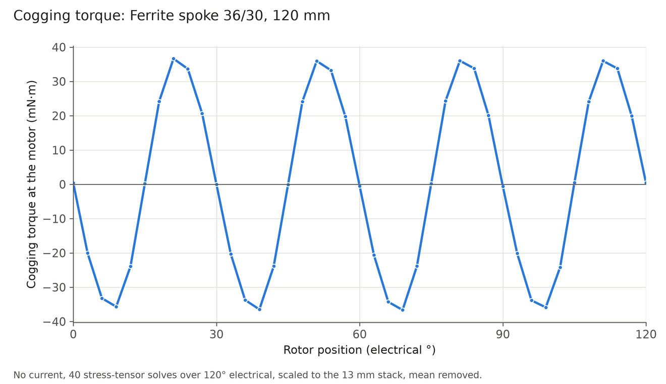
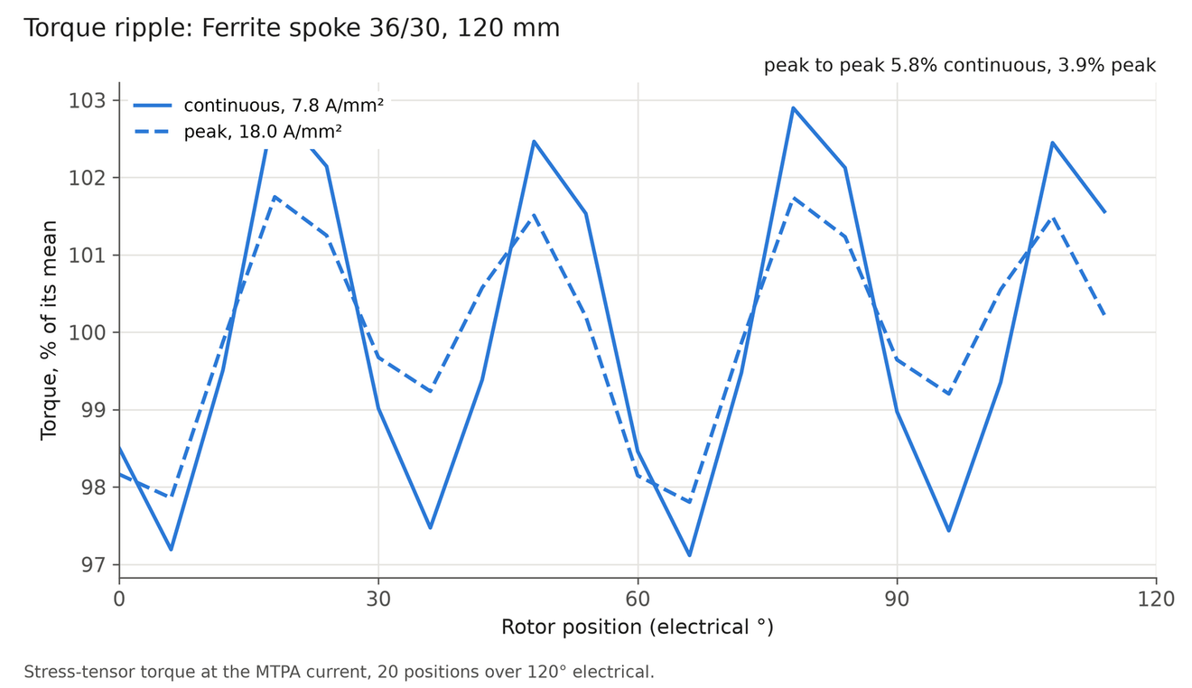
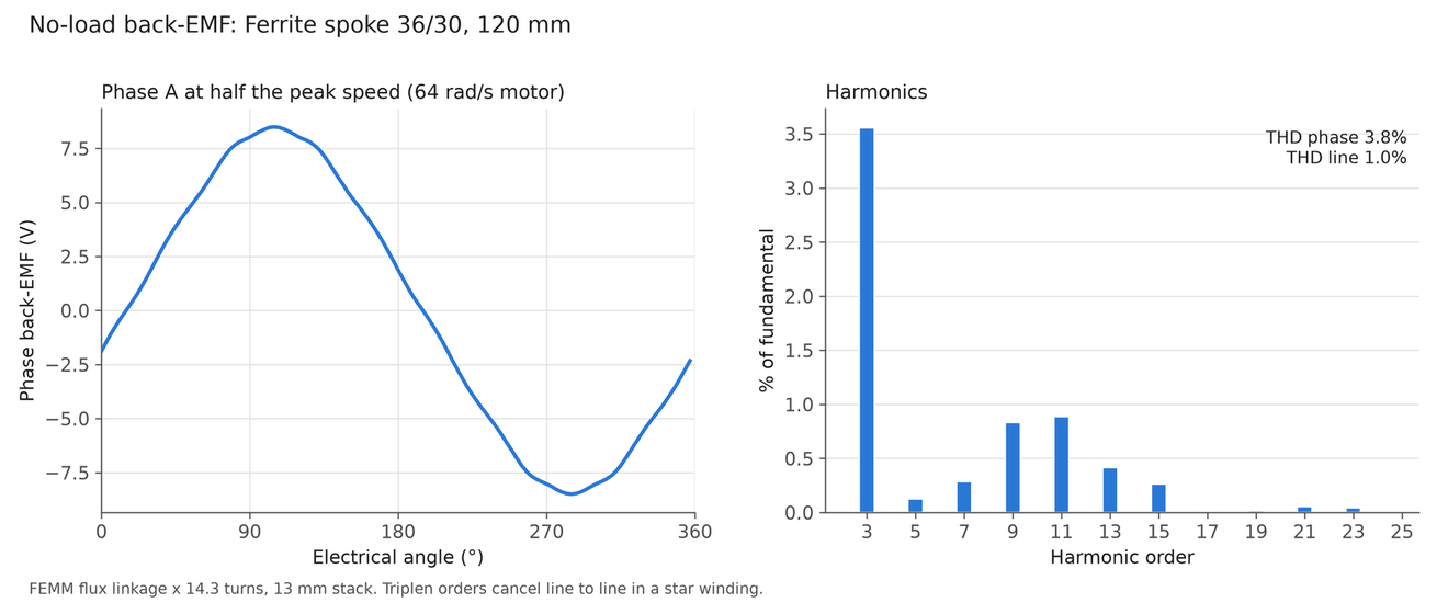
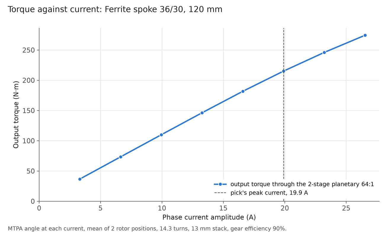
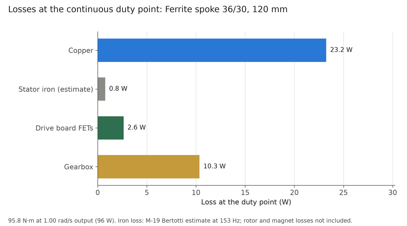
Torso pitch. NdFeB: 104 mm motor with an 11 mm stack, 48 slots and 56 poles, in a 110 × 42 mm actuator of 1.16 kg. Ferrite: 120 mm motor with a 13 mm stack, 36 slots and 30 poles, in a 124 × 45 mm actuator of 1.71 kg. The torso holds its pose on a brake, so the motor is sized for motion only. The torque-current and loss charts of the NdFeB torso motor are left out, because they were drawn for a 36:1 gearbox and the pick is 64:1.
Material cost estimate
A rough bill of materials for the 15 motors of one robot (seven joints in each arm and the torso). These are estimates for materials only, not quotes. A built motor costs far more than its materials at low volume, and manufacturing drives that cost, not the magnets. The assumed prices are NdFeB N42 at $60 to $120/kg, ferrite at $3 to $10/kg, magnet wire at $12 to $18/kg, M-19 steel at $2 to $4/kg and 1010 steel at $1 to $2/kg.
In the main case ferrite needs more than twice the active material and three times the magnet mass, but its magnets are far cheaper, so the total materials cost about the same. In the backdrivable and quasi-direct-drive sets the ferrite motors grow so much that their materials cost more.
| Item (15 motors) | NdFeB | Ferrite spoke |
|---|---|---|
| Active material, main set | 2.0 kg | 4.5 kg |
| Magnet mass, main set | 0.27 kg | 0.83 kg |
| Magnet cost, main set | $16 to $33 | $2 to $8 |
| Total material, main set | $23 to $44 | $19 to $36 |
| Total material, backdrivable set | $36 to $67 | $64 to $119 |
| Total material, quasi-direct-drive set | $67 to $125 | $74 to $141 |
Electronics and limits of the per-joint study
Both optimised variants use my own electronics architecture: 48 V DRV8363 gate drivers with a 100 V FET stage, an STM32G474 on the logic board, and the support and brake boards. Only the REVA power stage is laid out in KiCad. The other boards are simulated, not laid out, so a pick that needs a different board outline is a simulated board.
Iron loss is only a stator estimate. Cogging torque is not in the backdrive torque. There is no thermal FEM: the temperature limit uses one heat-transfer coefficient calibrated on stock actuators. Gearbox flex is one stiffness number. The MuJoCo check welds the base. These are screening results, not qualification. All of this is simulation, and nothing has been built.
Solved 3D flux overlays for the joint motors
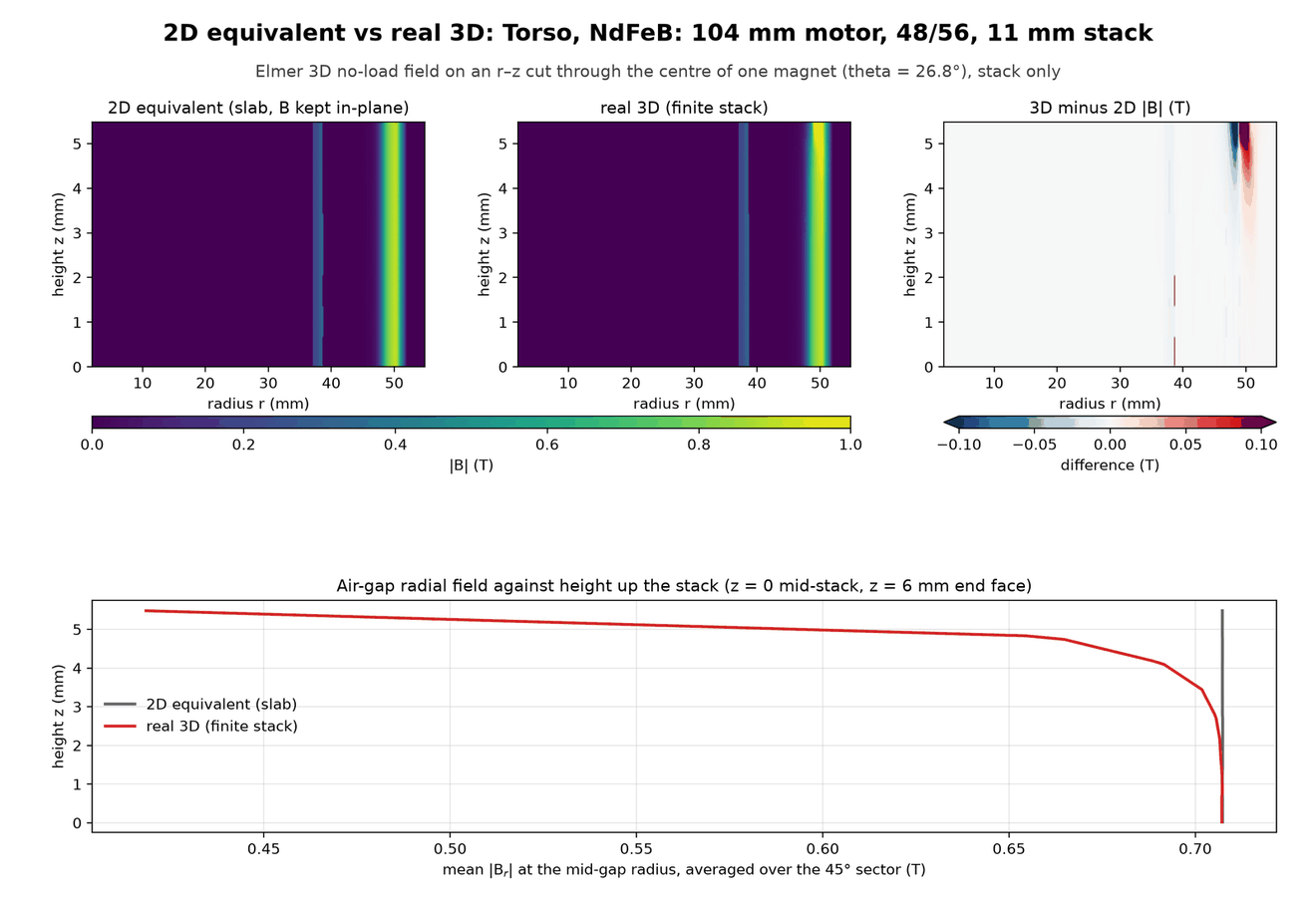
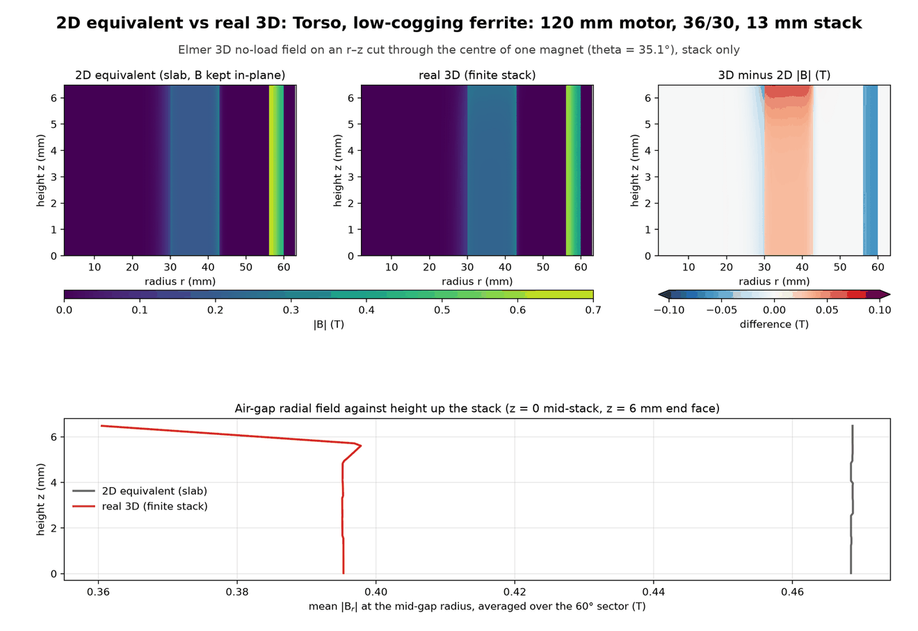
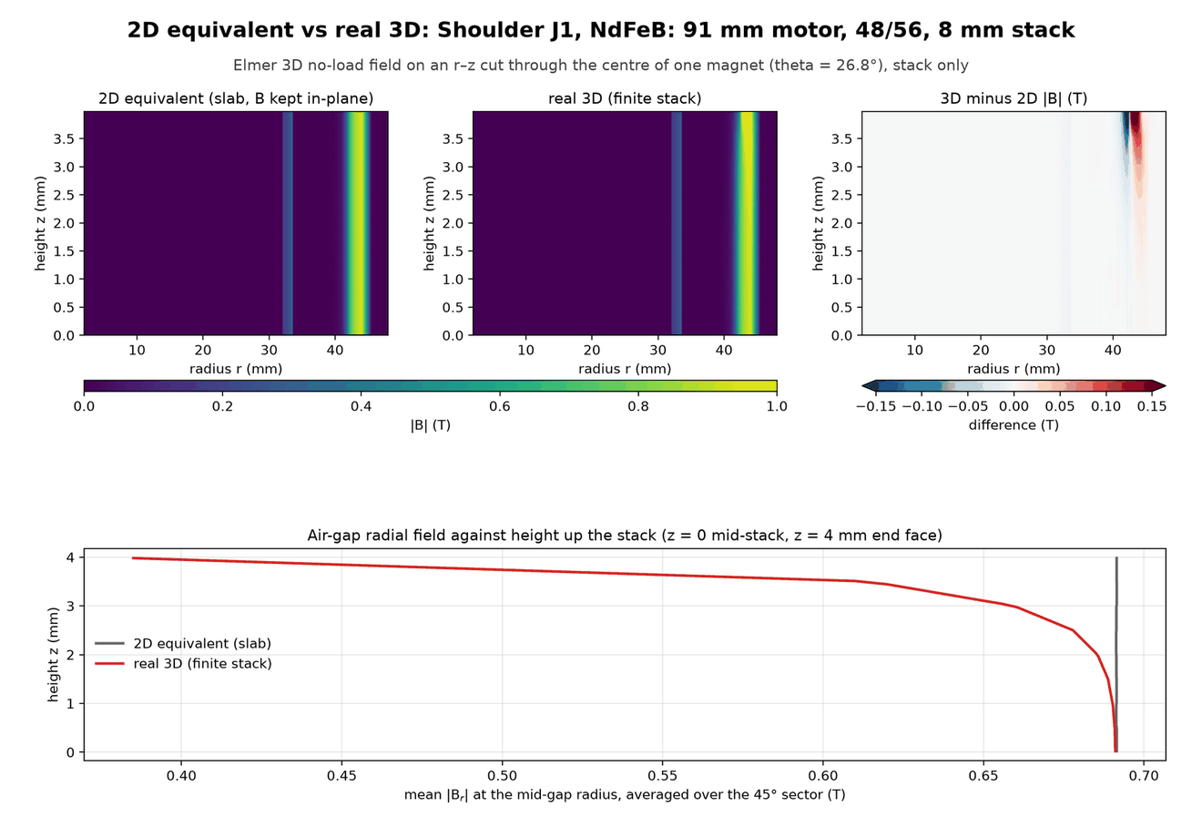
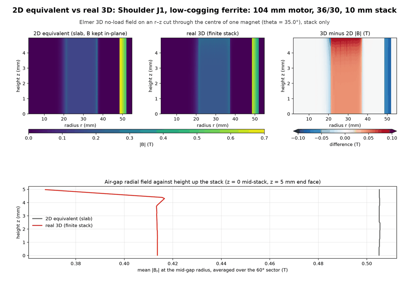
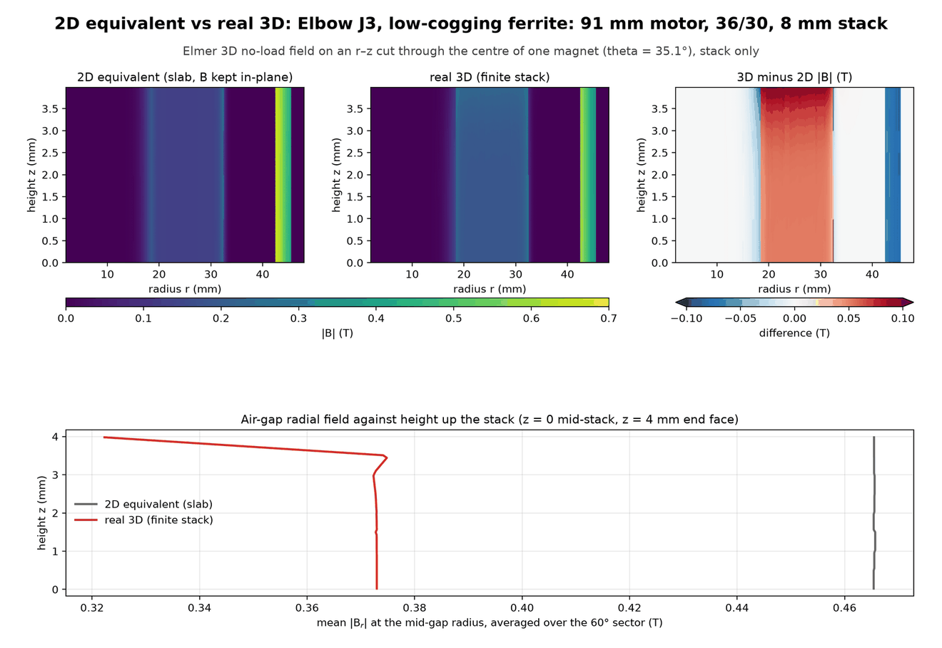
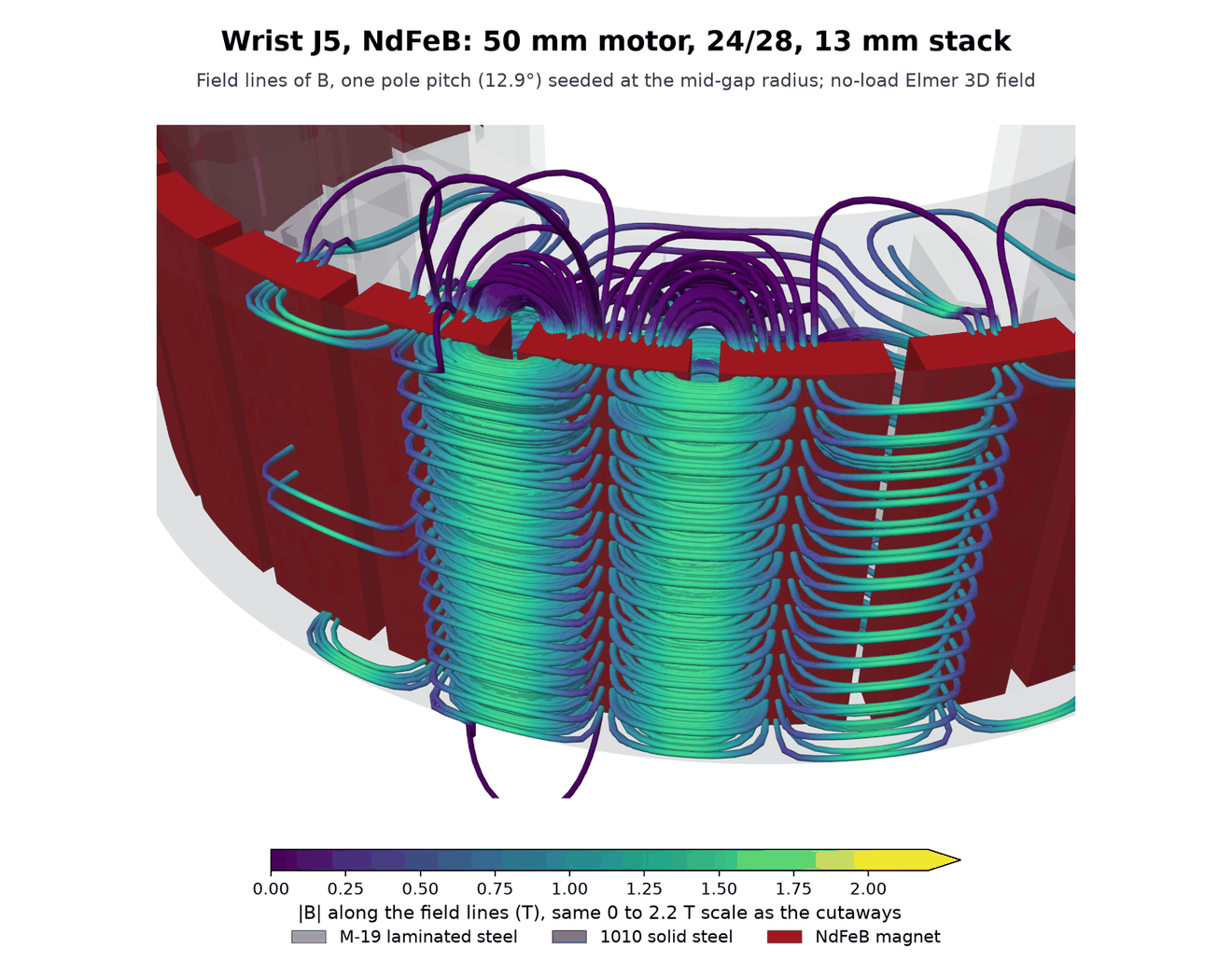
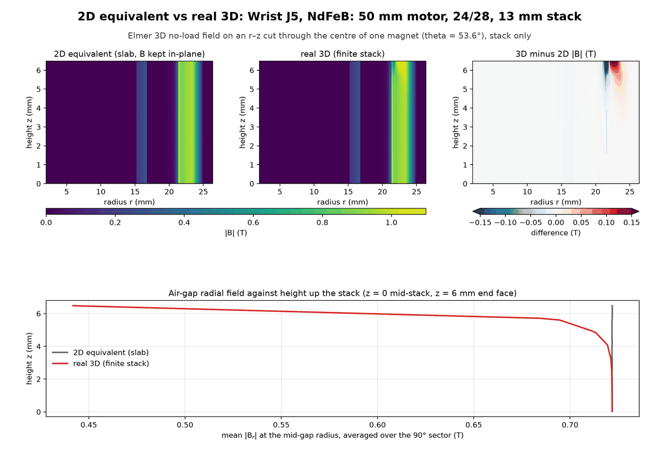
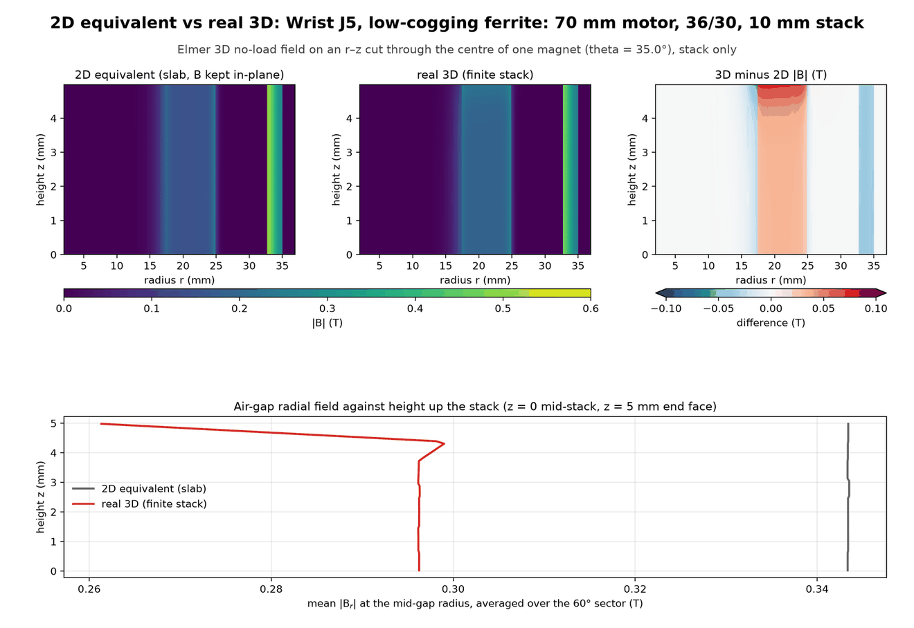
All 16 Elmer solves are complete: a 2D-equivalent slab and a finite-stack model for each of eight motors, at its picked stack length. The slab flux linkage agrees with FEMM to about 1%. The table gives finite-stack flux linkage divided by slab flux linkage. Equivalent end loss is the stack length multiplied by the fraction lost.
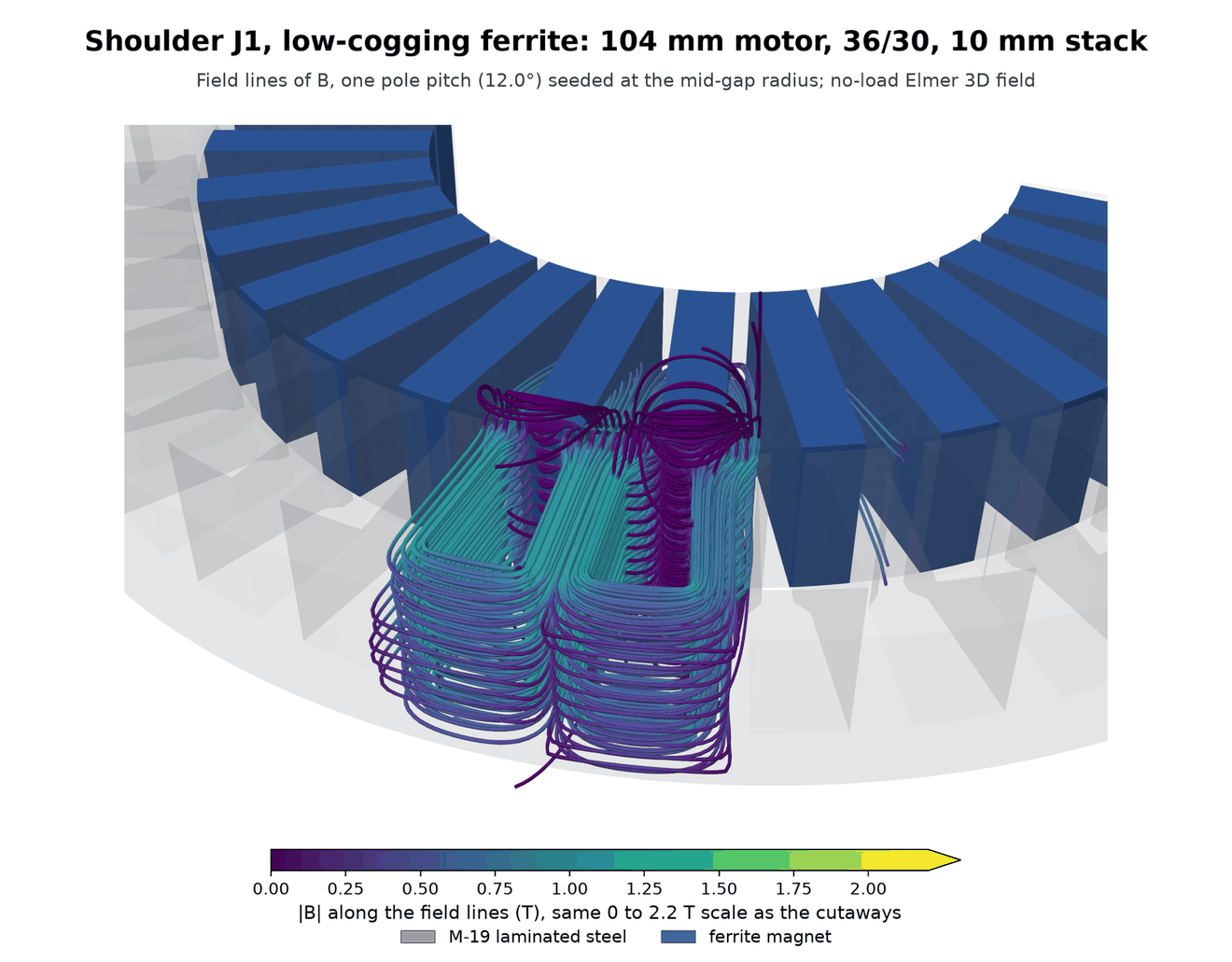
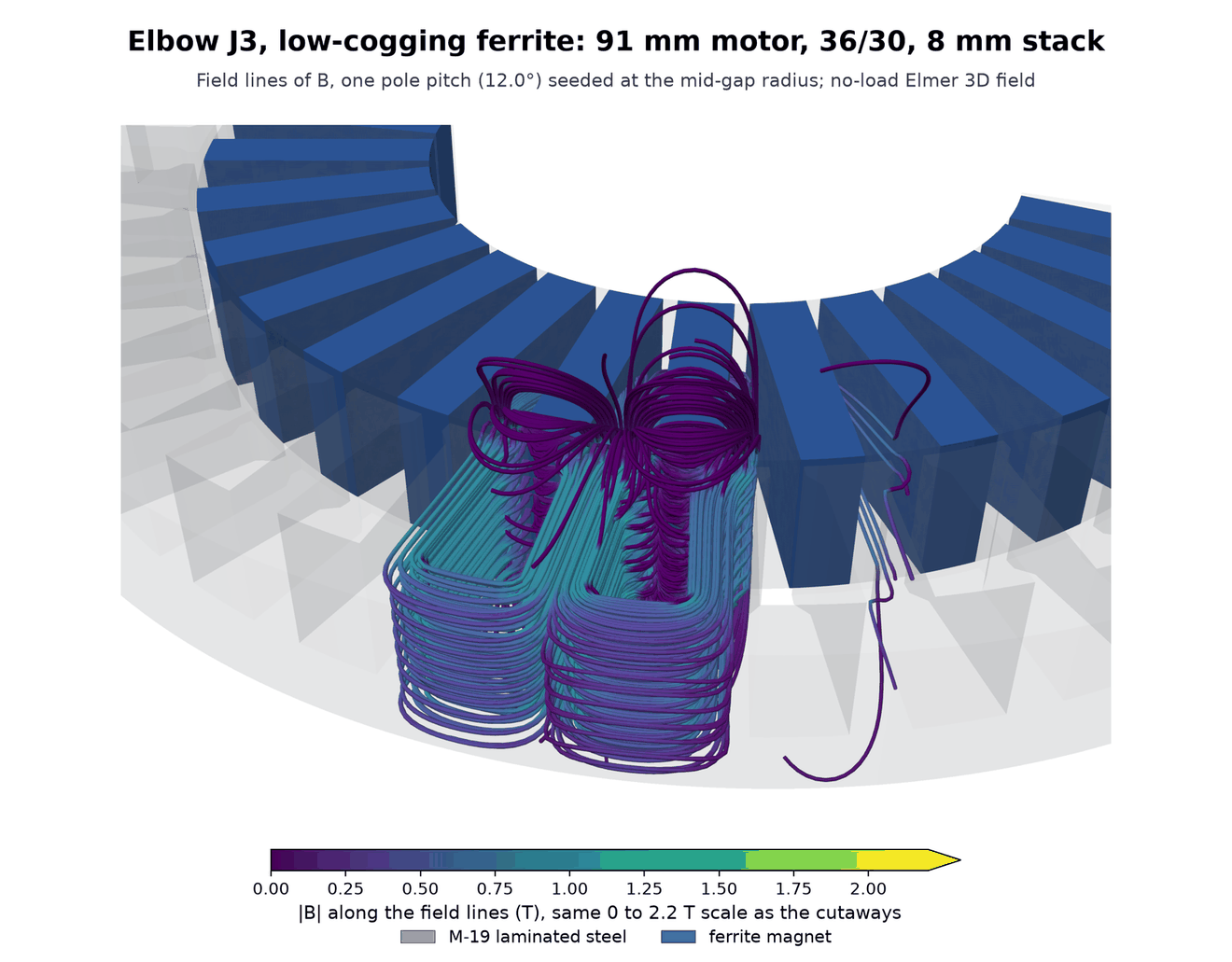
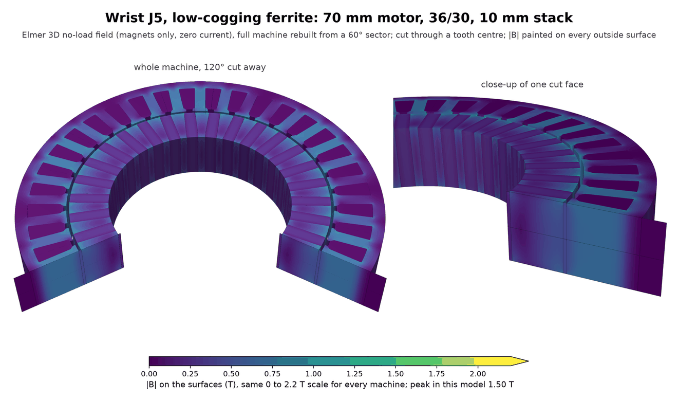
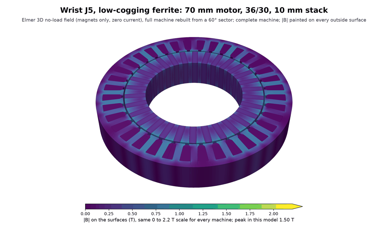
These new views compare the main NdFeB picks with the low-cogging ferrite picks, which all have 30 poles. That ferrite set weighs 5.45 kg per arm against 3.68 kg for NdFeB and still fails the 70% mass criterion at every joint. The earlier 24-pole arm plots above document the original mass-only optimisation, whose cogging was too high.
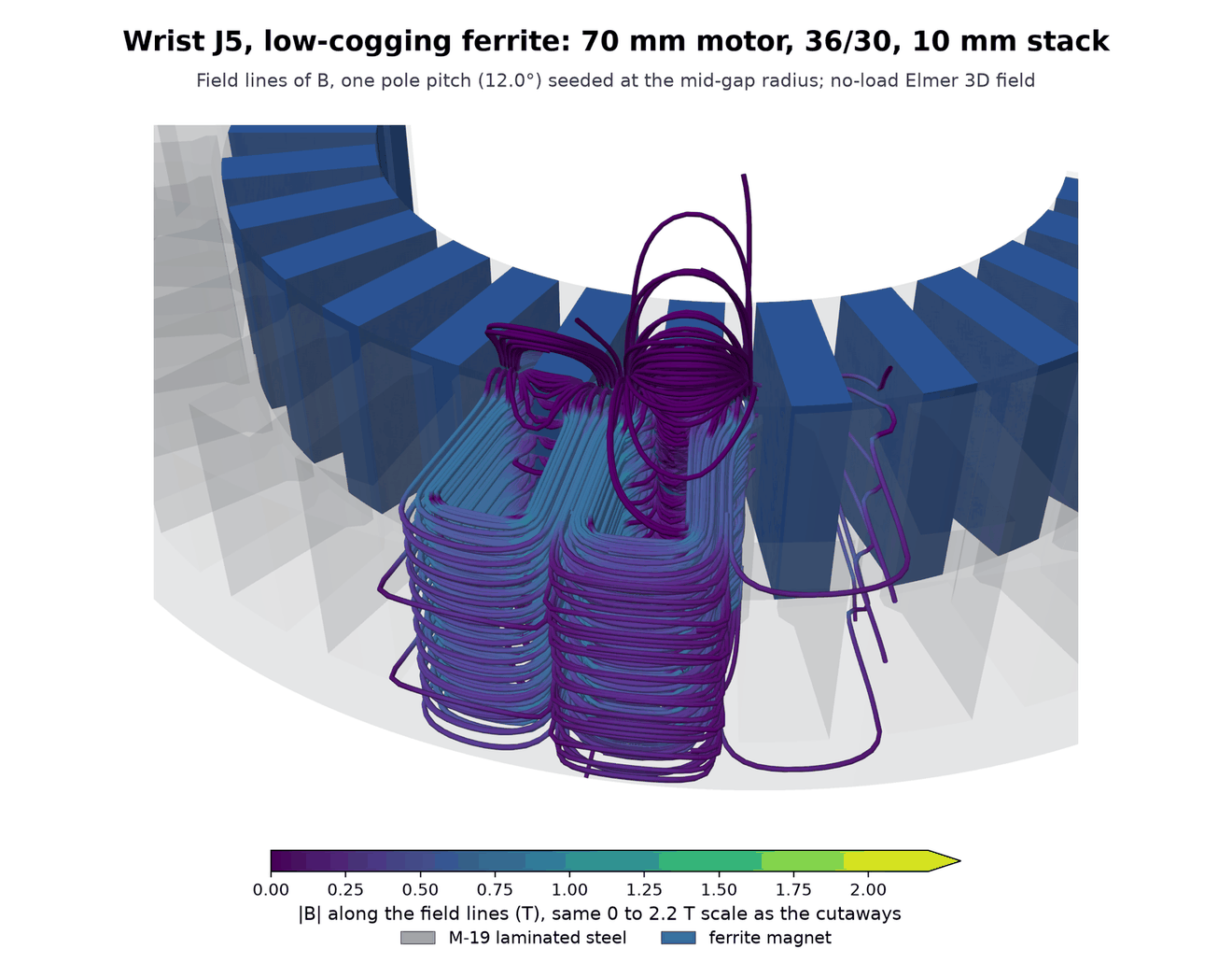
The colours are the solved magnetic flux density mapped onto the motor surfaces and cut faces. Each full machine is reconstructed from its solved sector and the mid-stack mirror. These are no-load fields from the permanent magnets, with zero winding current, at one rotor position. They show end leakage; loaded torque, heating and demagnetisation need their own checks. The gearbox, housing and controller boards are outside these field models.
NdFeB retains 96.9% to 98.7% of its slab flux; ferrite retains 86.1% to 90.6%. Ferrite's equivalent end loss grows to 1.44 mm at the torso, compared with the 1.11 mm assumed in sizing. This is a check on that assumption, not a new coupled optimisation with the measured losses substituted.
| Joint and motor | Motor diameter × stack | Slots / poles | Flux retained | Equivalent end loss |
|---|---|---|---|---|
| Shoulder J1, NdFeB | 91 × 8 mm | 48 / 56 | 97.7% | 0.19 mm |
| Shoulder J1, low-cogging ferrite | 104 × 10 mm | 36 / 30 | 87.1% | 1.29 mm |
| Upper arm J3, NdFeB | 80 × 6 mm | 48 / 56 | 96.9% | 0.19 mm |
| Upper arm J3, low-cogging ferrite | 91 × 8 mm | 36 / 30 | 86.1% | 1.11 mm |
| Wrist J5, NdFeB | 50 × 13 mm | 24 / 28 | 98.7% | 0.16 mm |
| Wrist J5, low-cogging ferrite | 70 × 10 mm | 36 / 30 | 90.6% | 0.94 mm |
| Torso pitch, NdFeB | 104 × 11 mm | 48 / 56 | 98.5% | 0.16 mm |
| Torso pitch, low-cogging ferrite | 120 × 13 mm | 36 / 30 | 88.9% | 1.44 mm |
Shoulder J1: solved 3D fields
Upper arm J3: solved 3D fields
Wrist J5: solved 3D fields
Torso pitch: solved 3D fields