← Darsh Patel

Neural-network motor control: PMSM and EESM

EMPE Lab · Summer 2026 · simulation and FEM only AI-drivenFeasibility study

On this page

I built a pipeline that learns motor flux maps from finite-element solves and uses them to generate current references for field-oriented control. A random forest performed best on independent off-grid points for the small IPM motor. For the electrically excited motor, the selected model depends on the sampling and tuning study; the comparisons are below.

An IPM neural-network implementation also placed and routed on a Lattice ECP5 at 29 MHz. All control results are from FEM, fixed-point comparisons or Simulink. The controller has not run on a motor.
EESM flux-map dataset ↗ · IPM flux-map dataset ↗ · PMSM fault dataset ↗ · code ↗

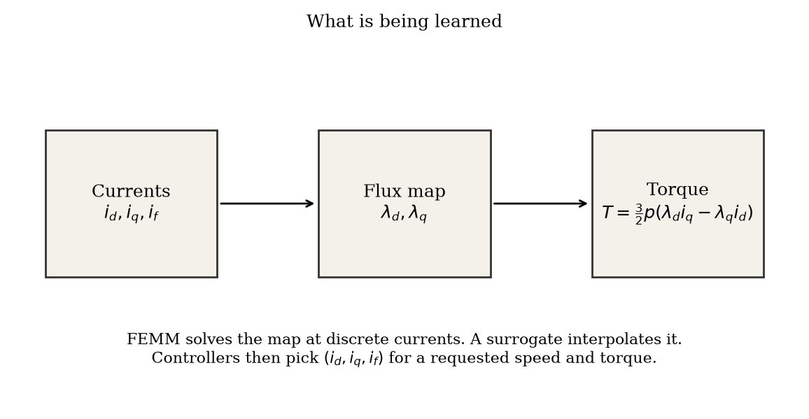
What the model learns: currents in, d- and q-axis flux linkage out, and torque computed from those fluxes.
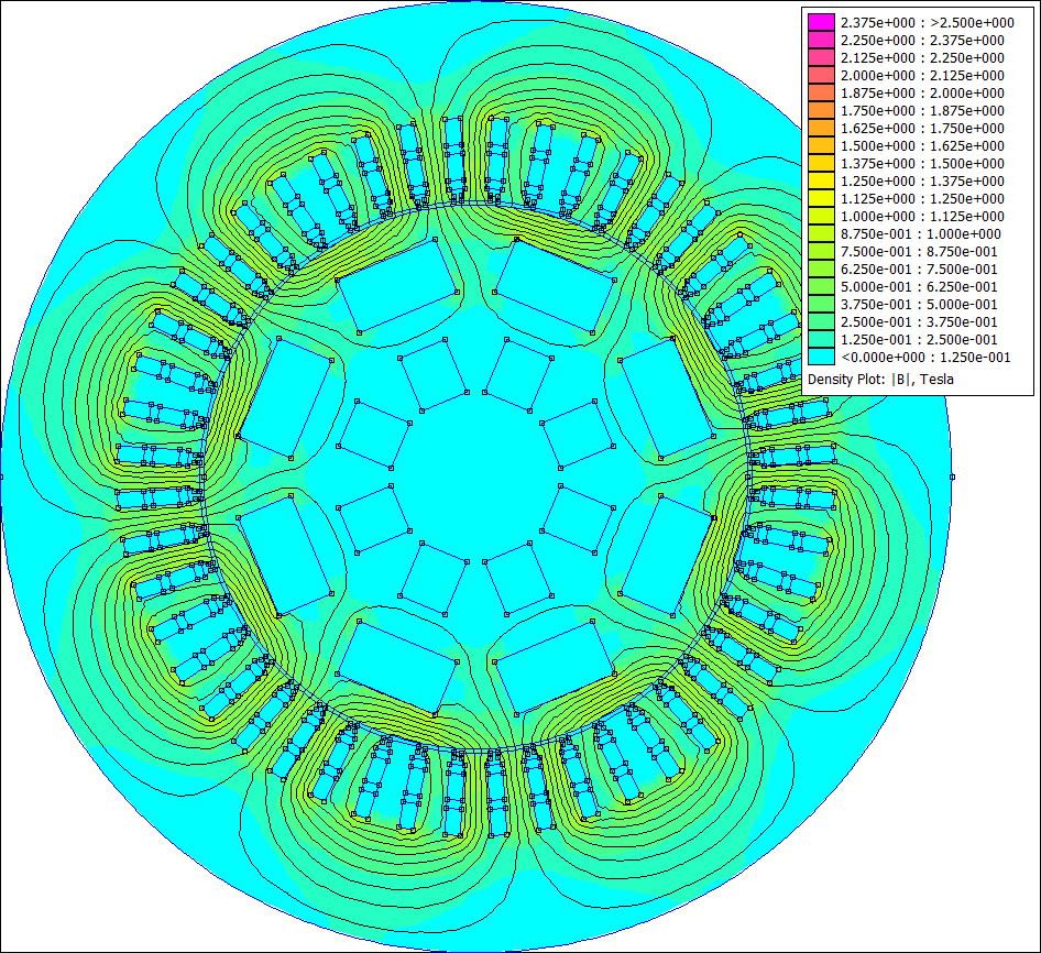
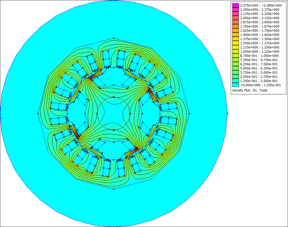
FEMM field plot of the four-pole EESM, with stator slots around a wound rotor, coloured magnetic flux density and black flux contours.
The four-pole EESM in FEMM: a full 360° cross-section of the stator and wound rotor, at i_d = 0 A, i_q = −30 A and i_f = 2 A. Colour shows magnetic flux density |B| on a 0–2.5 T display scale; black contours trace the flux. This is a saved magnetostatic solve, not a hardware measurement.
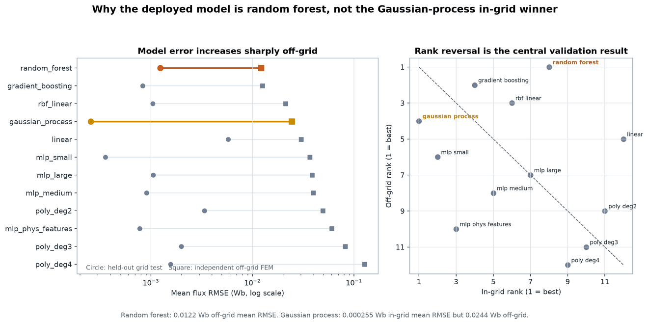
IPM motor: twelve surrogates ranked on held-out grid points (circles) and on 20 independent off-grid FEM solves (squares). The in-grid winner, the Gaussian process, drops to fourth off-grid.
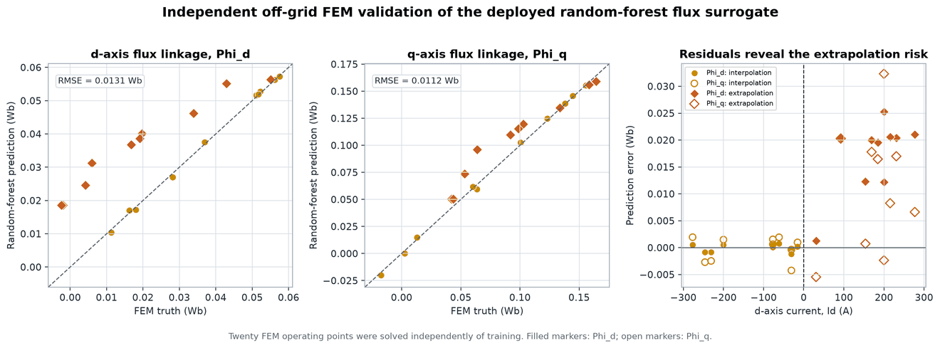
The random forest against the 20 off-grid FEM solves. Points inside the training range fit closely; the large misses are at positive i_d, outside the training grid.
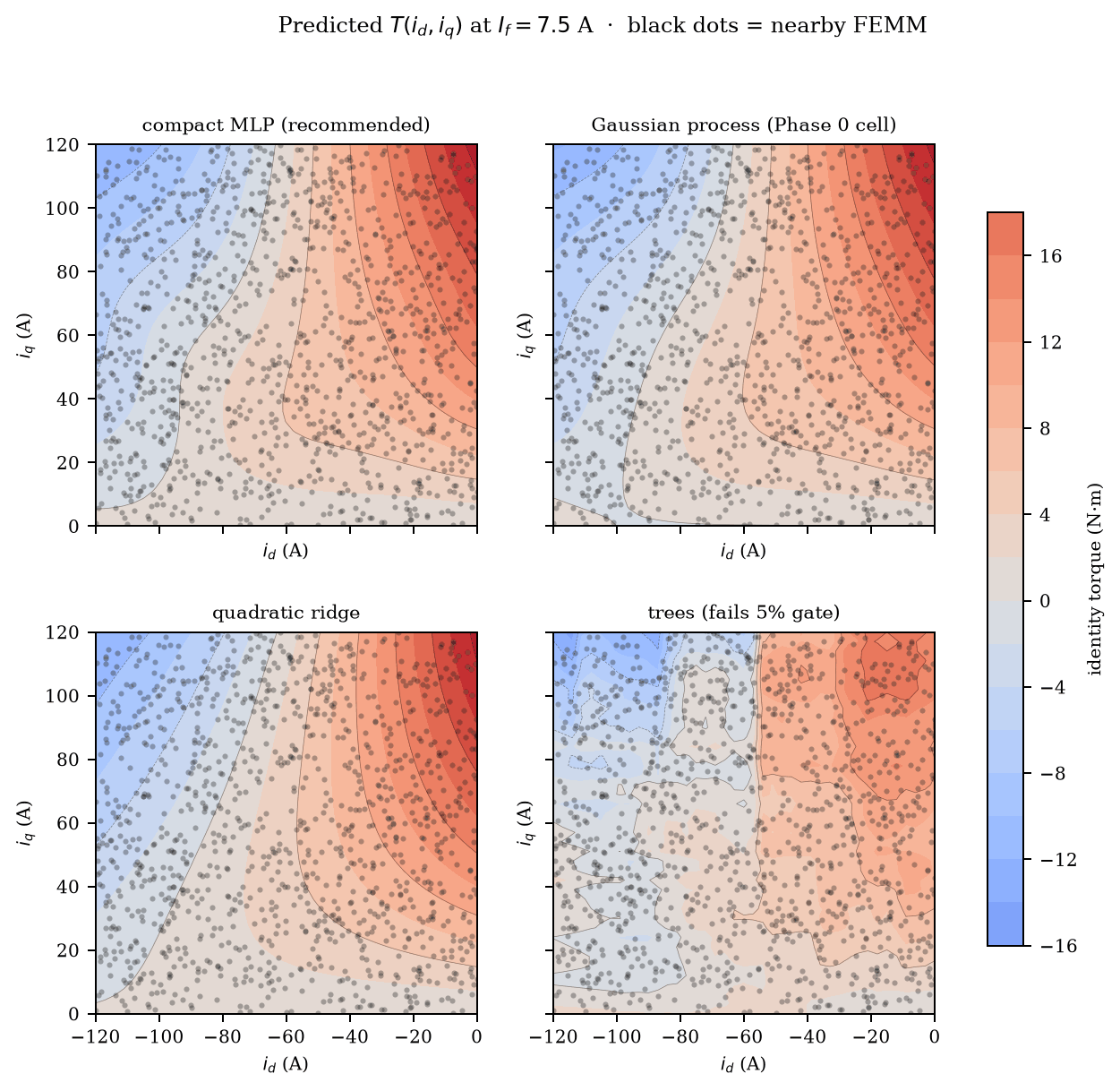
EESM torque from four learned maps at 7.5 A field current, with nearby FEMM solves as dots. The MLP and Gaussian process are smooth; the tree ensemble is blotchy and fails the torque-error gate.
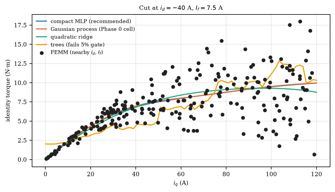
A cut at i_d = −40 A: the MLP and Gaussian process overlap and the trees stair-step. The dots are FEMM solves near the cut, not on it, so they scatter.

Flux-map modelling and validation

For a small IPM (permanent-magnet) motor, I scripted Ansys Maxwell 2D Student through Python to solve a 40 × 40 grid of 1,600 operating points. First I had to find why every non-zero-current solve was failing: inherited mesh operations pushed the mesh past the Student element limit. I then compared twelve surrogate models, from polynomials and a Gaussian process to four MLPs. The Gaussian process won on held-out grid points (0.000255 Wb RMSE) but fell to fourth on 20 independent off-grid FEM solves, where a random forest did best (0.0122 Wb). The off-grid winner feeds the MTPA and field-weakening search that builds the (speed, torque) → (i_d, i_q) reference table.

The electrically excited synchronous machine (EESM) adds the rotor field current as a third input. For a four-pole, 10 kW academic design I ran a 1,759-point FEMM campaign and compared four model families across three sampling strategies and three training budgets, 36 combinations in all, each scored against a sealed set of 256 solves. The frozen ranking picked a Gaussian process trained on 256 Latin-hypercube points, at 0.37 N·m torque RMSE. In a later study with equal tuning for every family, the compact MLP had the lowest median error, 0.079 N·m, and 0.096 N·m on a separate 48-point boundary holdout. That study measured spread across training draws, so it didn't replace the frozen pick.

FPGA implementation

I also ported the small IPM MLP to fixed-point Verilog. Across a 61 × 61 current grid its output stays within 0.29 mWb of the floating-point model, and it places and routes on a Lattice ECP5 at 29 MHz.

Extension: inter-turn fault detection

The same drive signals can show when a motor is failing. This extension, which I started in September 2026, aims for an InstaSPIN-style detector: commission a motor it has never seen, learn that motor's healthy baseline, then flag faults from the drive's own currents and voltage commands, on a microcontroller's NPU, with no extra sensors.

I built a fast fault simulator for PMSM, BLDC, SynRM and PM-assisted SynRM drives, with switched PWM, dead time, BLDC six-step and FEMM flux maps of faulted machines. Every dataset is split by motor, so the test motors are never seen in training. Stage 1 compares angle-synchronous harmonics of each window against the motor's own commissioning statistics. Stage 2 is an 8,024-parameter int8 CNN that names the fault type; it reaches 79% balanced accuracy across eight classes, and I compiled it for the TI F28P55x NPU with TI's toolchain and linked it into C2000 firmware.

Inter-turn shorts are the current focus. With switched-inverter data and the threshold set for 1% false alarms, the detector catches 91% of shorts covering 10–21% of a phase and 71% at 5–10%, but few below 2%, where the fault looks like a healthy motor's own asymmetry. On held-out motors false alarms run 3–5%, above the 1% target, and six-step BLDC drives are the weak case. These are simulated motors: the firmware hasn't run on the LaunchPad and the detector hasn't seen a real fault yet.
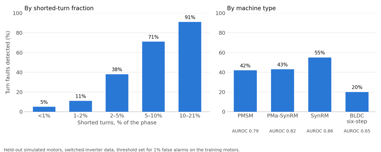
Inter-turn short detection on held-out simulated motors, by severity and by machine type.
FEMM cross-section of the fault-study BLDC motor, showing magnetic flux around the rotor and through the stator teeth.
BLDC model from the fault-study simulator, shown in FEMM at a healthy geometry-check operating point. Colour shows |B| on a 0–2.5 T display scale, with black flux contours. These checks show the saved models solve; they are not calibrated motor measurements.
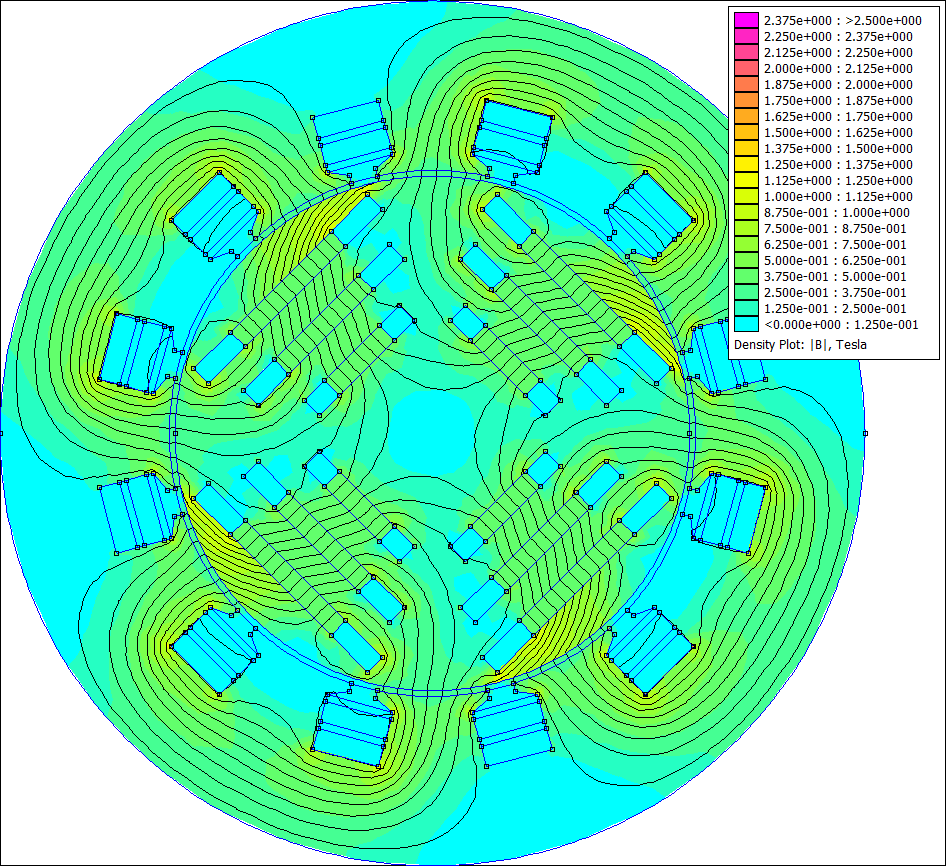
FEMM field plot of a synchronous reluctance motor with flux barriers in its rotor.
Synchronous reluctance motor (SynRM): the rotor's flux barriers steer the field through its iron paths. A saved healthy geometry-check solve, on the same 0–2.5 T display scale.
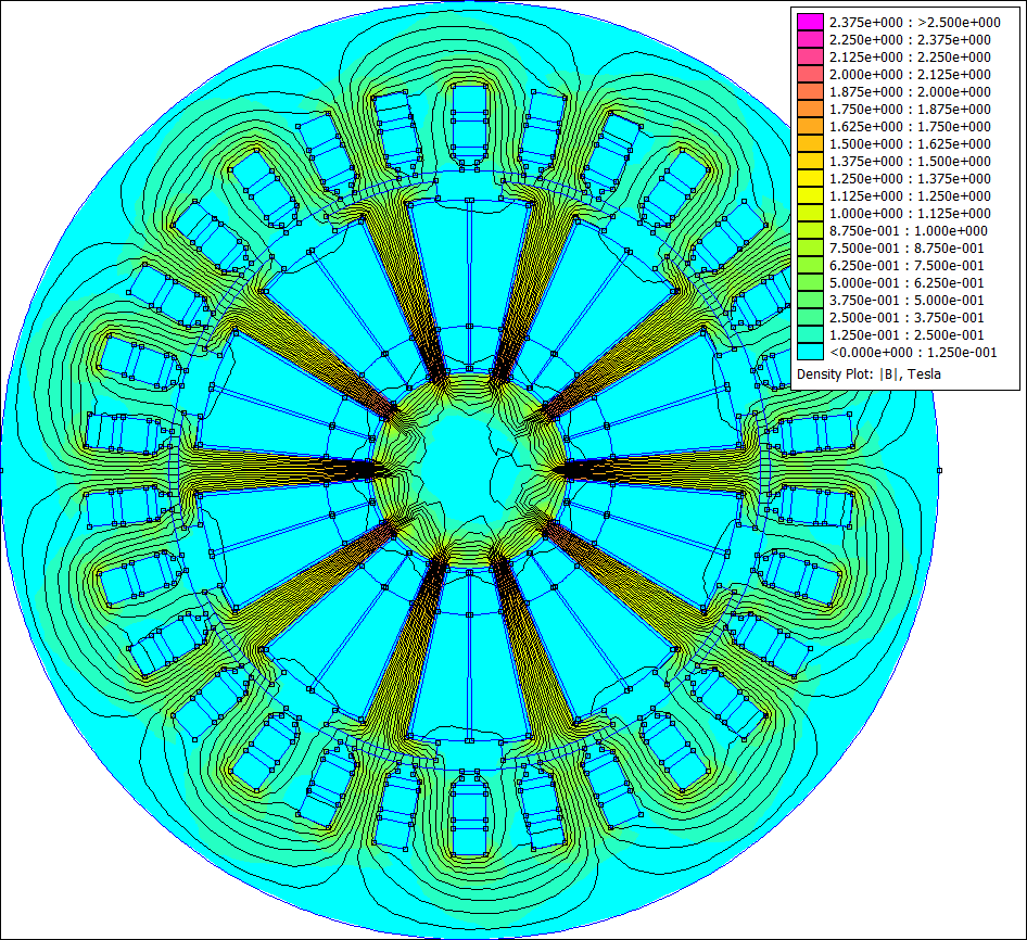
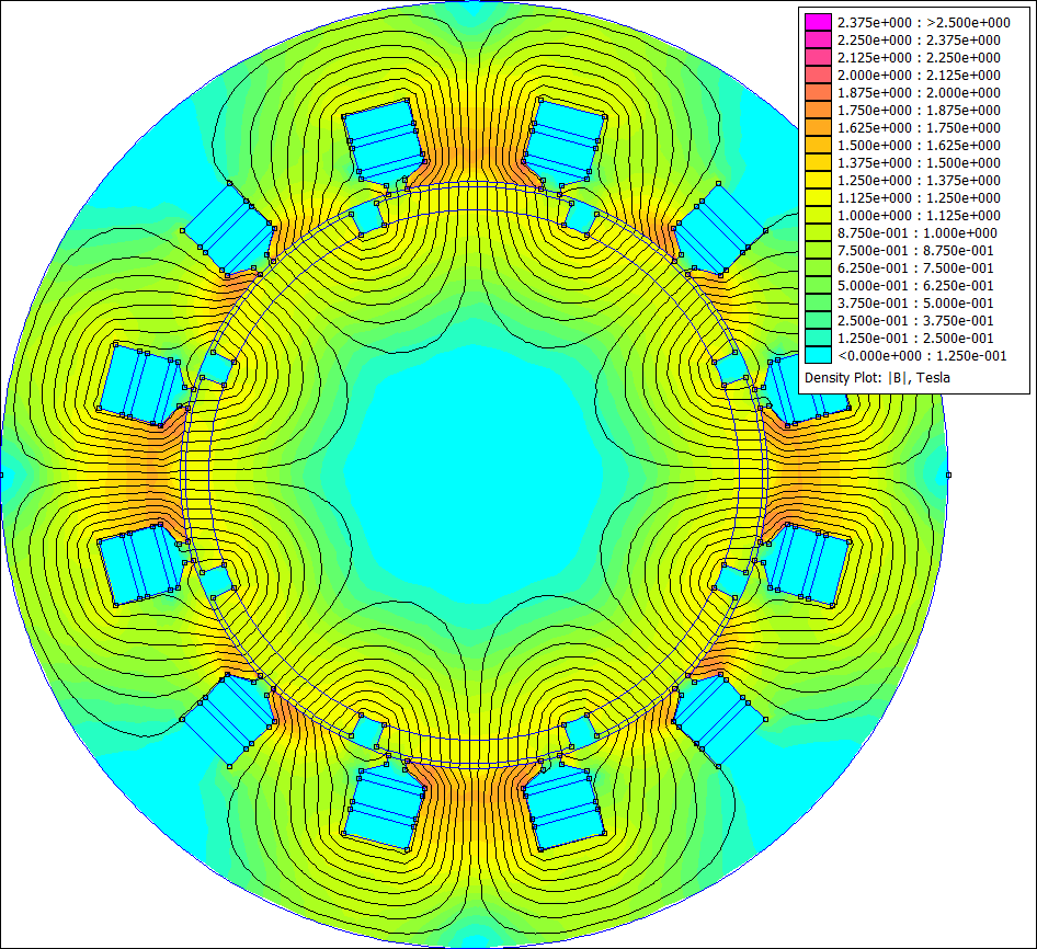
FEMM field plot of the fault-study permanent-magnet-assisted synchronous reluctance motor.
PM-assisted SynRM: permanent magnets added to the reluctance rotor. This is a separate fault-study model, shown at a healthy geometry-check point, rather than the small Maxwell IPM used above. Same 0–2.5 T display scale.
FEMM field plot of the fault-study electrically excited synchronous motor with a 30-slot stator and wound rotor.
The fault-study EESM, with a 30-slot stator and rotor field winding. This is a separate geometry from the four-pole EESM used for the learned flux maps above. A saved healthy geometry-check solve, on the same 0–2.5 T display scale.