Humanoid upper body
I am designing the motor-controller and power PCBs for a mobile humanoid based on MABEL. Every actuator-control PCB design is unfinished and unvalidated. The custom boards have not been fabricated, assembled or tested on hardware. The renders, KiCad checks, calculations and simulations document design work in progress.
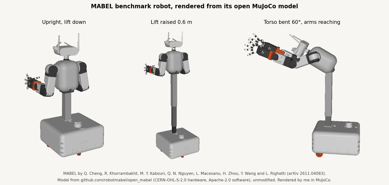
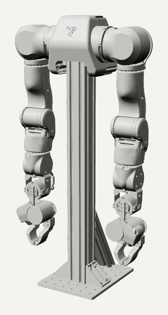
The mechanical design is MABEL, an open mobile bimanual robot by Qilong Cheng, Rooholla Khorrambakht, Mohamed Yassine Kabouri, Quang Nam Nguyen, Luca Macesanu, Haoran Zhou, Yipeng Wang and Ludovic Righetti (arXiv 2611.04083). It has two 7-DOF arms derived from OpenArm 2.0, a lift, a torso pitch joint and a swerve drive base.
The joint actuators are bought; my round power-stage boards replace their controllers, with a logic board stacked above each one. A support board powers each arm. The electronics target a 20 to 54 V input for this robot. The operating range still needs hardware testing. The motor-sizing study and inductive position-sensor concept are linked below.
What still needs to be finished
The common logic board and the WGG and P96 power boards still need routing, review of the remaining KiCad findings, and mechanical fit checks. The support board, brake resistor strip, external capacitor bank and both DF40 breakouts are routed. Their fabrication files are available for review. Fabricator checks, parts fit, assembly and first-article inspection are still open for all boards.
Hardware bring-up and validation are still ahead. Check the DF40 mating orientation and continuity, the controller firmware and interfaces, the DC bus and protection circuits, and the brake chopper and thermostat. Measure current, temperature and regeneration under the intended motor loads and duty cycles. The board-level simulations still need comparison against measurements.
Base design: MABEL
A useful humanoid needs more than arms: it also has to raise its arms, bend over and move around. MABEL does all three, with a desk-column lift, a torso pitch joint and a swerve drive base under two OpenArm-derived 7-DOF arms. The MABEL team published the CAD and a full MuJoCo model under CERN-OHL-S-2.0 and Apache-2.0, which is what makes it usable as a base design. All of the analysis below runs on their unmodified model.
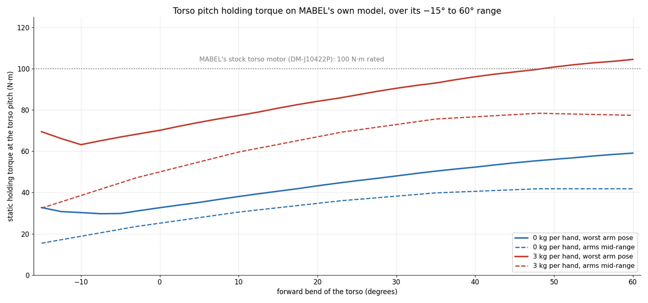
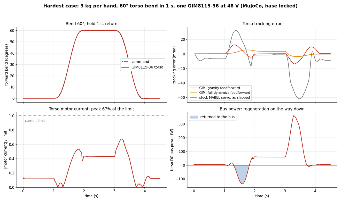
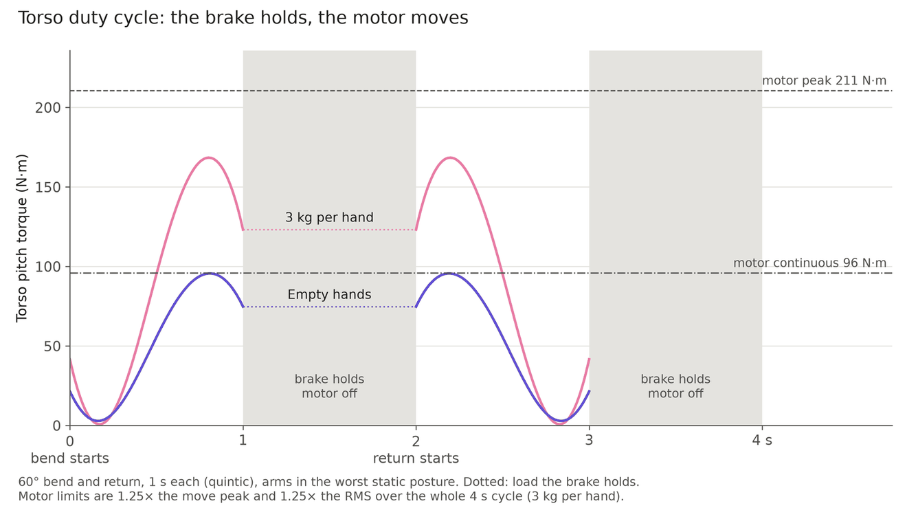
The torso pitch joint is the new demanding joint. Holding a 60° forward bend takes 59 N·m with empty hands and 104 N·m with 3 kg in each hand. That matches the 100 N·m rating of MABEL's own torso motor and its 3.5 kg-per-arm static limit. The lift, base and hands stay as MABEL designed them.
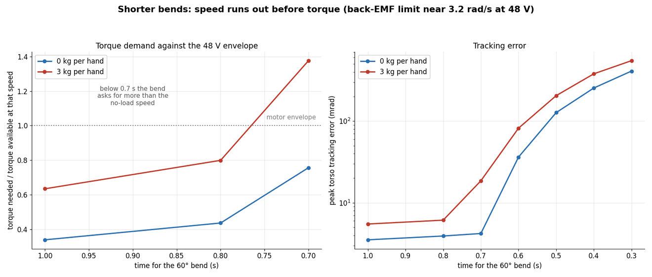
My version replaces the joint drives with my own 48 V controller boards. As a first check, the MuJoCo model swaps the torso and arm actuators for GIM geared motors driven at 48 V, with a current loop, voltage limit and gearbox friction. One GIM8115-36 makes the 60° torso bend in 1 s with 3 kg per hand at 67% of its current limit. Speed runs out before torque: bends shorter than about 0.7 s hit the back-EMF limit. Holding a loaded bend costs about 60 W in the windings, so the torso needs a brake or counterbalance. The NdFeB-optimised and rare-earth-free-optimised versions of each joint come from the rotor study. Their results are in the next section.
These are simulations with the base locked in place. Gearbox friction and rotor inertia are assumed, not measured.
Optimised actuators vs stock on MABEL
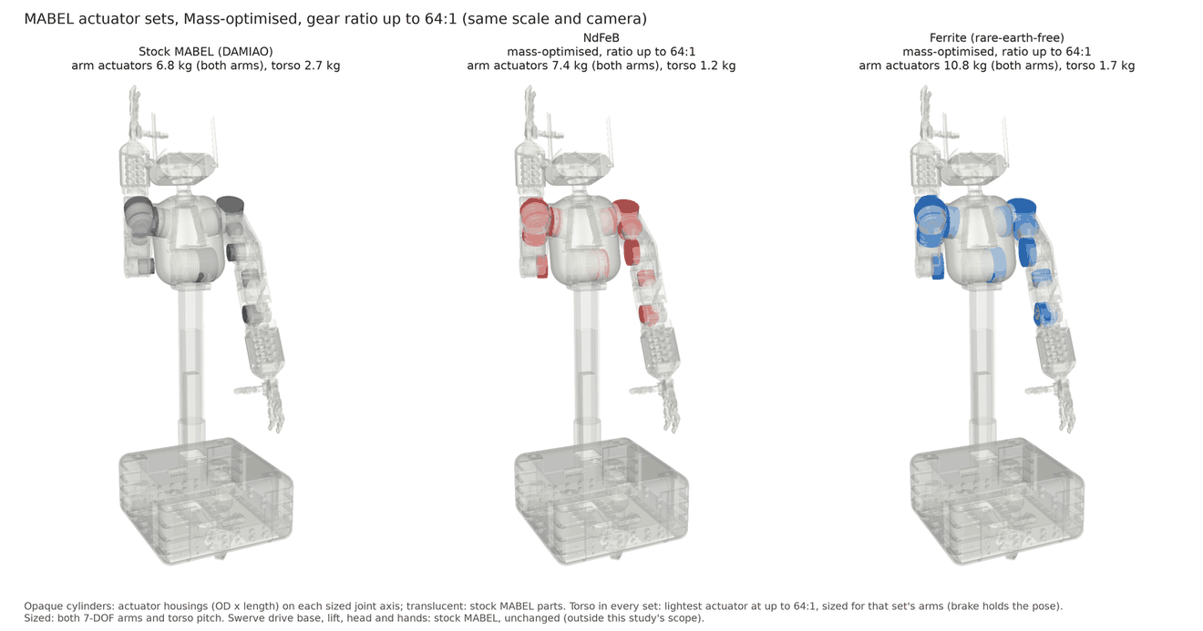
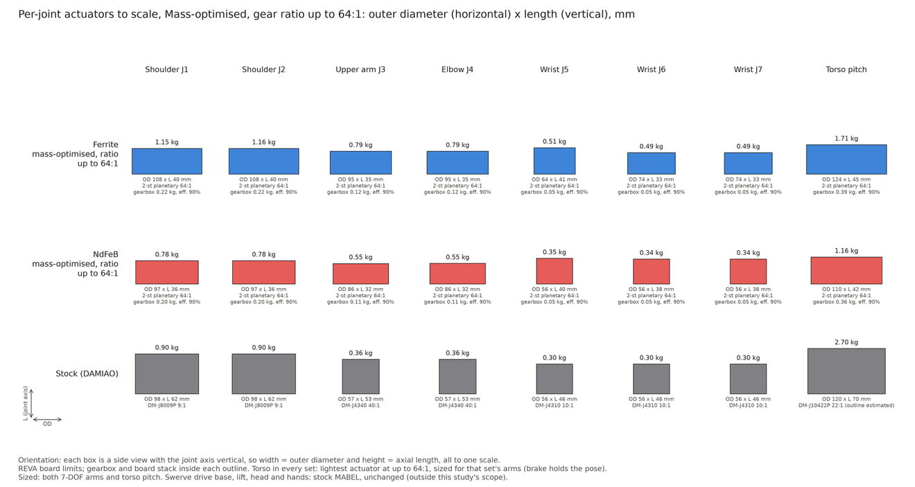
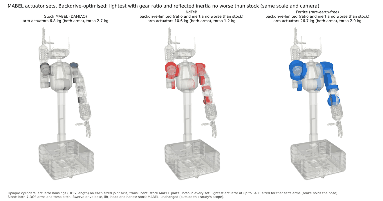
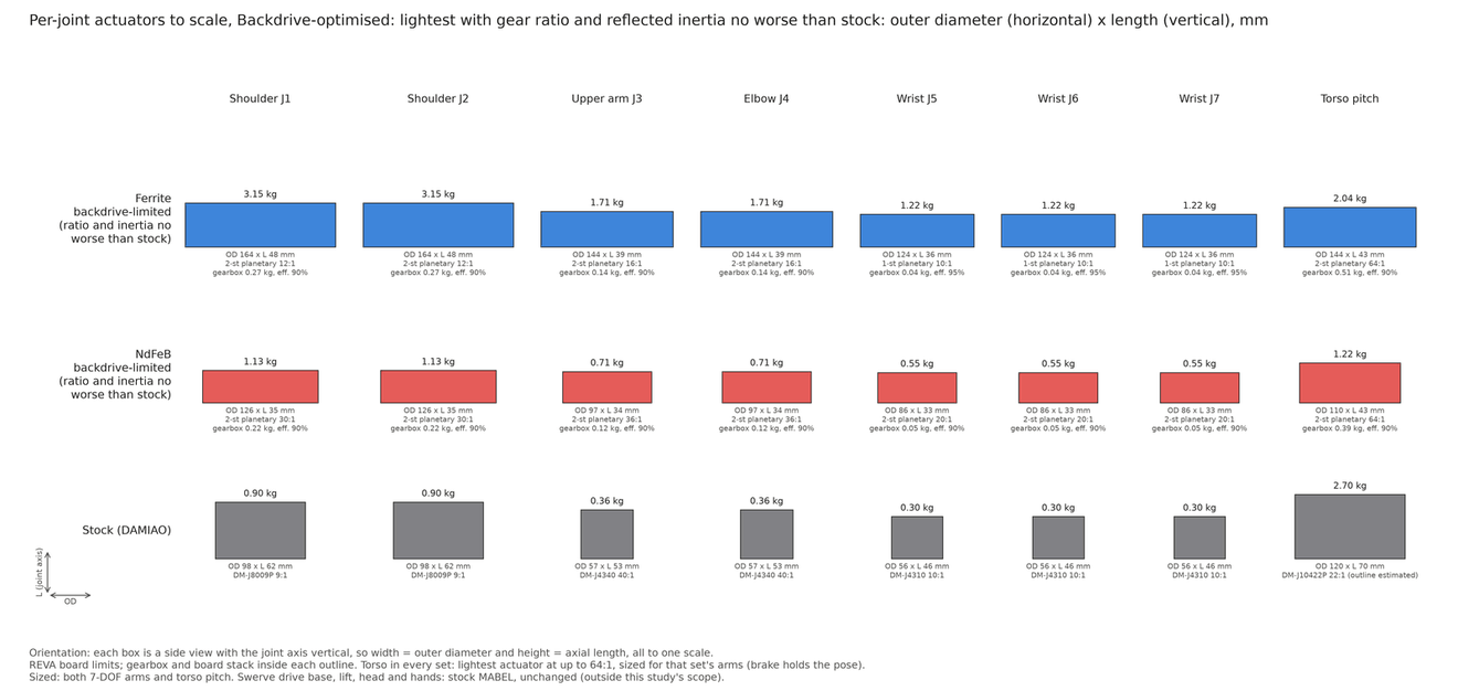
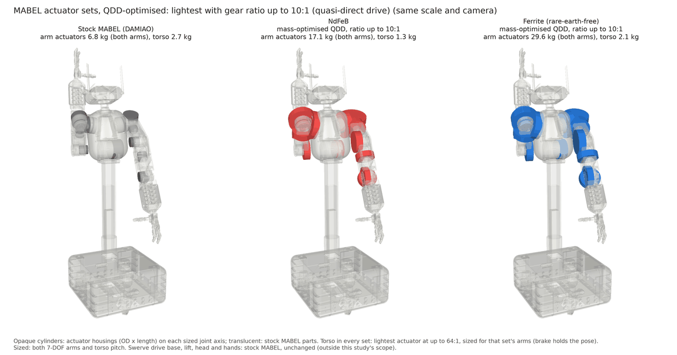
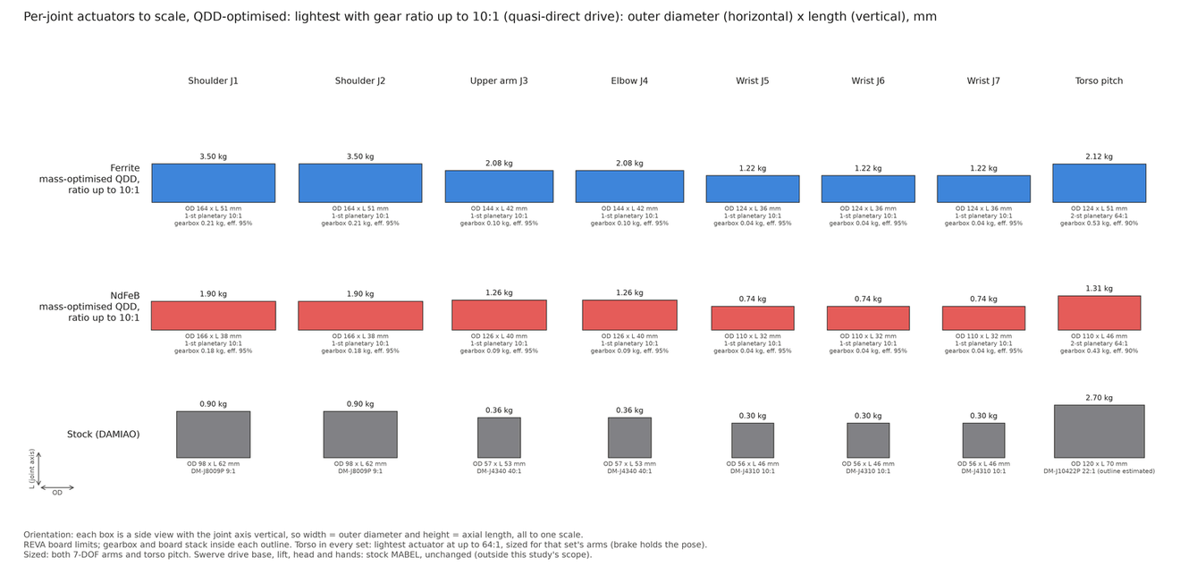
The rotor study sizes an actuator for each arm joint and for the torso pitch joint of MABEL. Each actuator is a motor from a library of 145 FEMM designs, a gearbox, a housing and my 48 V board stack, chosen together to be as light as possible. There are two optimised variants of the arms and torso: one with NdFeB magnets and one with ferrite spoke rotors. Each variant is sized again with its own masses and gearbox inertia, because heavier actuators at the shoulder add load to the torso. The study calls this coupled sizing. The lift, head and hands are stock MABEL parts. The swerve drive in the base was not changed in any variant, because it was not in the design scope of this feasibility study.
MABEL is by Qilong Cheng, Rooholla Khorrambakht, Mohamed Yassine Kabouri, Quang Nam Nguyen, Luca Macesanu, Haoran Zhou, Yipeng Wang and Ludovic Righetti (arXiv 2611.04083, robotmabel.github.io/website). Every variant below is a change to their open model.
Both optimised variants use my own electronics architecture: 48 V DRV8363 gate drivers with a 100 V FET stage, an STM32G474 on the logic board, and the support and brake boards from this page. The WGG and P96 layouts are partly routed in KiCad. The plots in this section are numerical results for the actuator variants.
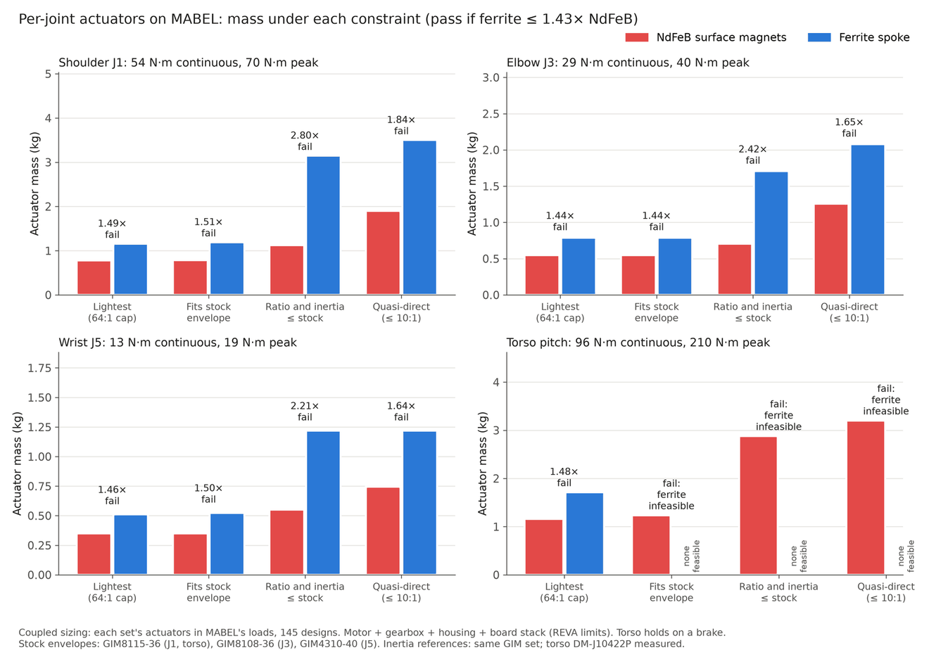
Mass. In the main case the gearbox is limited to 64:1 and each technology picks the lightest actuator that meets the joint's requirement. One arm's actuators weigh 3.68 kg with NdFeB and 5.38 kg with ferrite. For both arms the actuators weigh 6.8 kg in stock MABEL, 7.4 kg with NdFeB and 10.8 kg with ferrite. The torso actuator weighs 2.7 kg in stock MABEL, 1.2 kg with NdFeB and 1.7 kg with ferrite.
What stock means. In the mass and size comparisons, stock is MABEL's own DAMIAO actuators. In the MuJoCo and Simulink comparisons, stock is the GIM reference set (GIM8115-36, GIM8108-36 and GIM4310-40), because the electrical data of MABEL's DAMIAO actuators is not modelled.
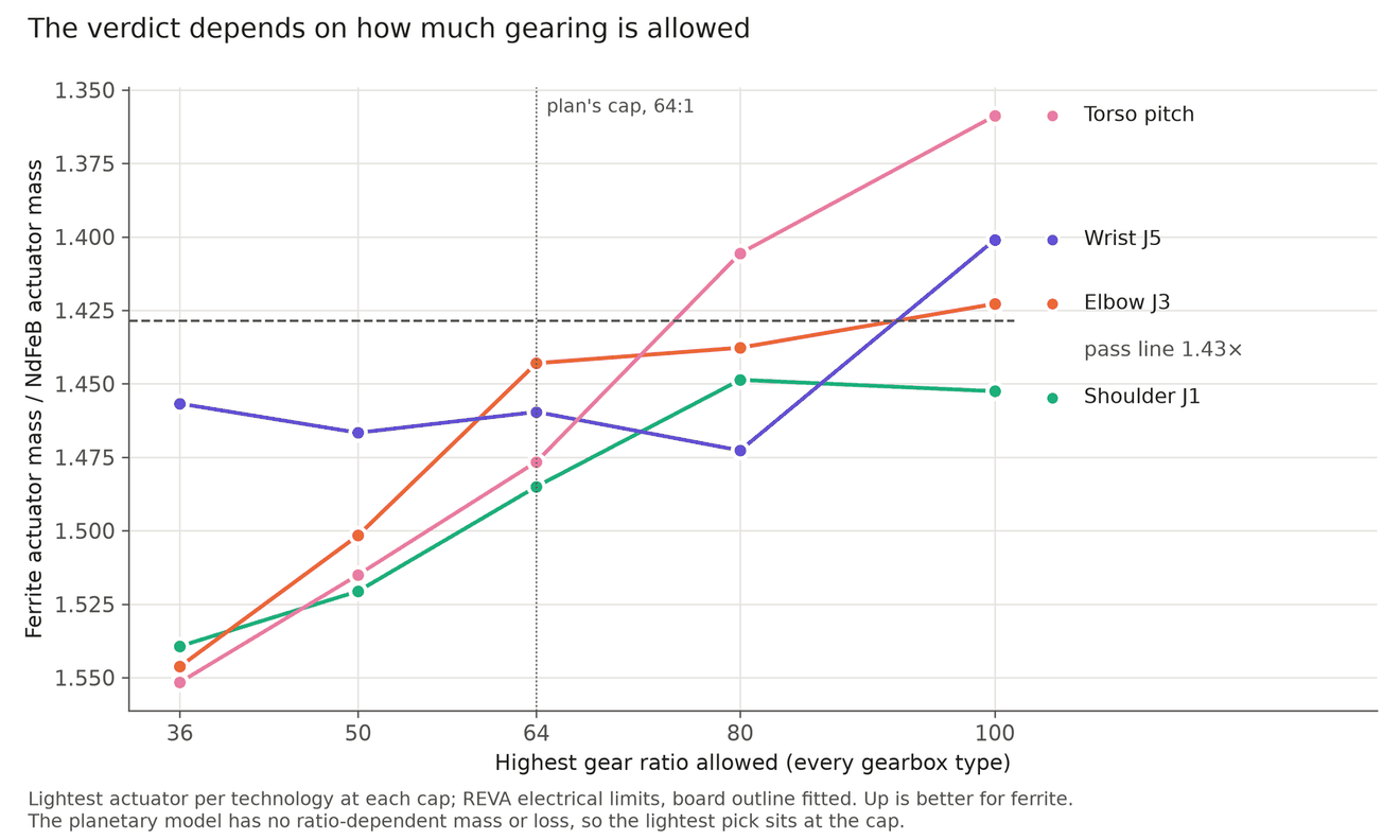
The 70% line. The original brief set the bar before any results: ferrite is close enough if its actuator weighs at most 1.43 times the NdFeB one, which is 70% of the NdFeB torque per kilogram. This is a judgement line from the brief, chosen before the results. It is not computed. In the main 64:1 case ferrite fails it at all four joints: 1.49 at the shoulder J1, 1.44 at the upper arm J3, 1.46 at the wrist J5 and 1.48 at the torso. The break-even cutoffs are 67% to 69%. The same picks pass at a 60% or 65% line and fail at 70%, 75% and 80%. The rotor study page has the per-joint detail.
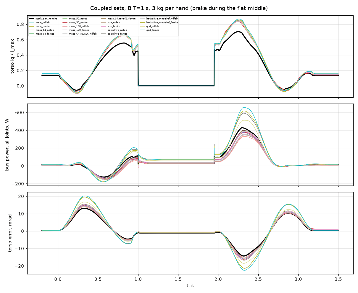
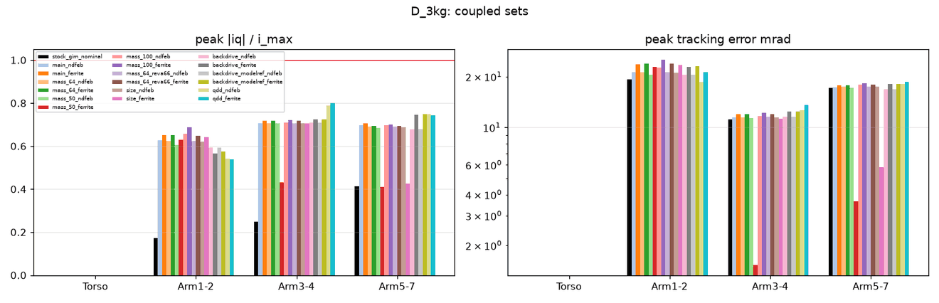
Whole-robot check in MuJoCo. Each set has its own robot model, made from MABEL's open MuJoCo model with the torso and arm actuators replaced: mass, inertia, armature, friction and force limit. The base is welded in place. Here stock is a set of GIM geared motors (GIM8115-36, GIM8108-36 and GIM4310-40) at 48 V, with a current loop, a voltage limit and gearbox friction. The pass rule and the controller gains were fixed before the runs. A set passes when no joint sits at a limit more than 2% of the time and the tracking error is at most the larger of 1.5 times the stock error and 10 mrad. In the torso bend, 60° in 1 s with 3 kg per hand, the stock torso draws 0.70 of its current limit and the optimised main sets draw 0.84. Their peak tracking error is 15.5 mrad with NdFeB and 16.7 mrad with ferrite, against 14.3 mrad for stock.
| Set | NdFeB, at low / nominal / high stock inertia | Ferrite, at low / nominal / high stock inertia |
|---|---|---|
| main (64:1) | pass / pass / pass | fail / pass / pass |
| mass_64 | pass / pass / pass | fail / pass / pass |
| mass_50 | pass / pass / pass | fail / pass / pass |
| mass_100 | fail / pass / pass | fail / fail / fail |
| mass_64_reva66 | pass / pass / pass | fail / pass / pass |
| size | pass / pass / pass | fail / pass / pass |
| backdrive | pass / pass / pass | fail / fail / fail |
| backdrive_modelref | pass / pass / pass | fail / fail / fail |
| qdd | fail / pass / pass | fail / fail / fail |
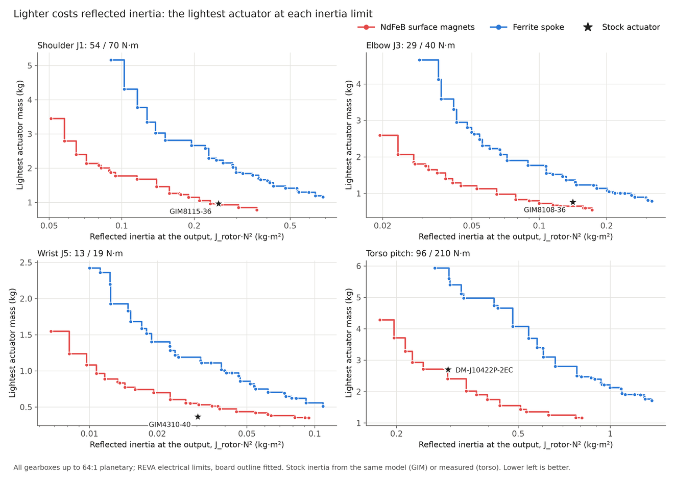
At the nominal stock inertia NdFeB passes in every set. Ferrite passes the main, mass_64, mass_50, mass_64_reva66 and size sets, and fails the 100:1, backdrive and quasi-direct-drive (QDD) sets. The mass_50 and size sets pick a different gearbox type for some ferrite joints, so they are not a like-for-like comparison. The backdrive and QDD sets limit the gear ratio and the reflected inertia, so they test how easily the arm can be pushed by hand.
Several of these verdicts are borderline. They flip with the reflected inertia of the stock actuator, which is an estimate from rotor geometry: 0.25 kg·m² for the GIM8115 and 0.14 kg·m² for the GIM8108 at nominal, with bounds of 0.156 and 0.130 (low) to 0.318 and 0.170 kg·m² (high). SteadyWin publishes no verified value. A bench measurement of the stock inertia would settle them.
Retuned gains. I also ran every set again after scaling the gains of each joint by that set's inertia relative to stock. All 18 sets pass at all three stock inertias. I made this change after seeing the results, so it is a sensitivity check and not part of the verdict above.
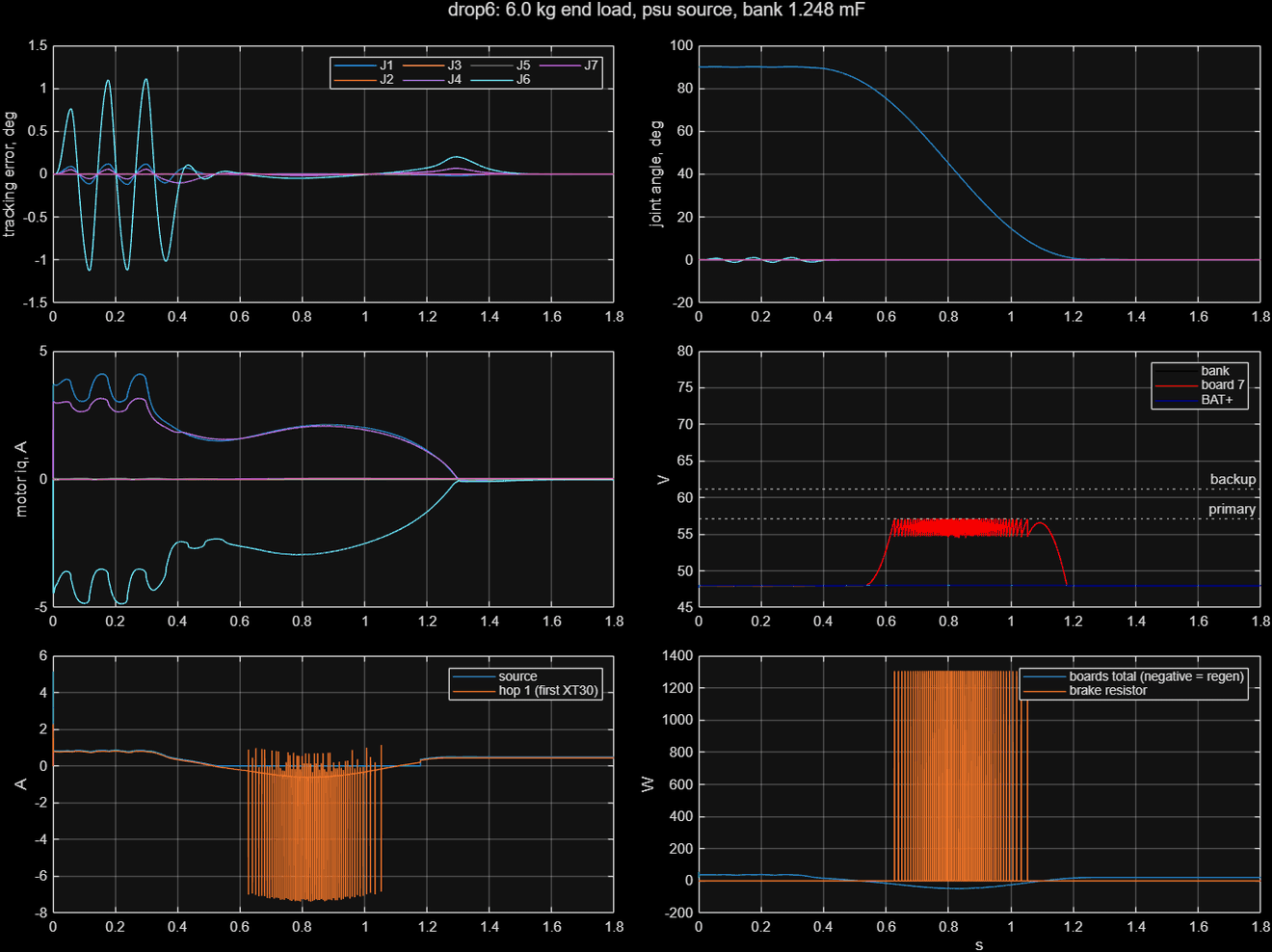
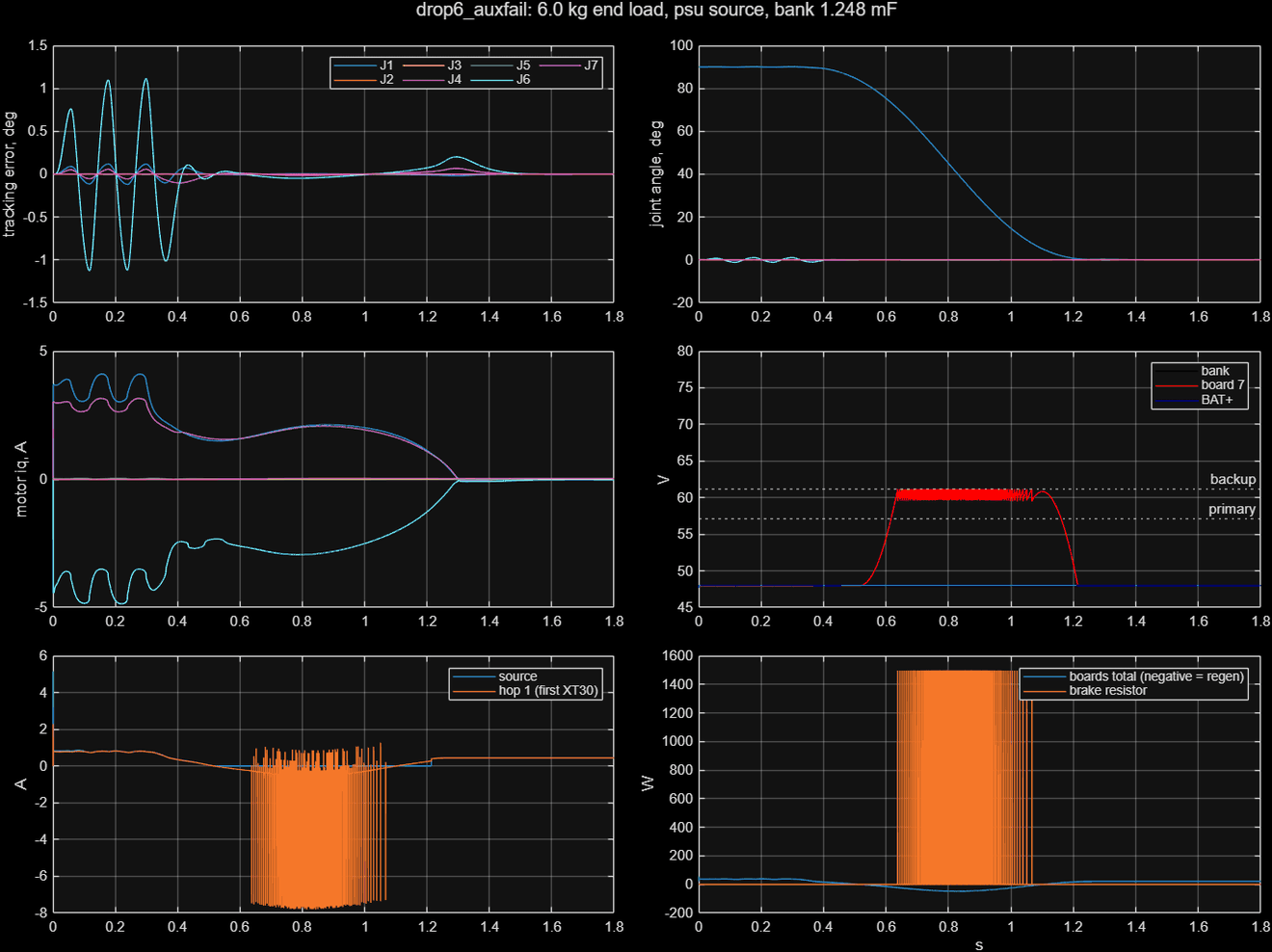
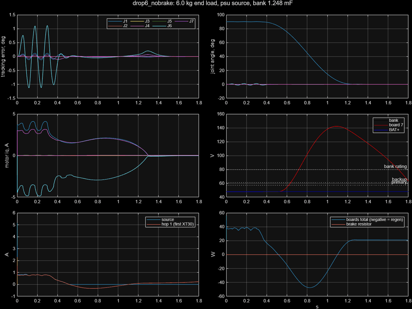
Simulink bus check. A Simulink model of one arm on the 48 V bus ran three scenarios (lifting 6 kg, lowering 6 kg, and lowering 6 kg with the aux supply lost) for stock and 16 optimised sets. All 51 runs complete without solver warnings. The peak bus voltage is 57.14 V to 57.16 V, or 61.19 V to 61.21 V with the aux supply lost, and the brake chopper sets both values. The brake energy for stock is 27.0 J lifting, 26.9 J lowering and 36.6 J lowering with the aux supply lost. Every set except the two QDD sets takes 24.4 J to 27.1 J in the lift and the drop. The ferrite QDD set is the worst, at 32.6 J and 44.6 J. This check covers one arm and no torso, and the variants only change the added mass in that model.
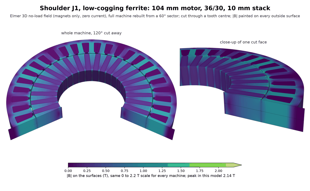
Cogging warning. The mass-only optimiser chose 36-slot, 24-pole ferrite spokes for most of the ferrite arm joints, including J1, J3 and J5 here. Those motors have a cogging torque of 20% to 38% of their continuous torque and a torque ripple of up to 45%, against 3.5% to 7.6% for 30-pole spokes. The library sweep did not compute cogging, so the optimiser could not see it. A low-cogging ferrite set with no 24-pole motors weighs about 1% more (5.45 kg instead of 5.38 kg for one arm in the main case) and gives the same verdict at every joint. The new 3D flux overlays at the end of this page use the low-cogging picks. The 24-pole ferrite plots here retain the original mass-only result; they are not the recommended design.
Limits. Iron loss is only a stator estimate. Cogging torque is not in the backdrive torque. There is no thermal FEM: the temperature limit uses one heat-transfer coefficient calibrated on stock actuators. Gearbox flex is one stiffness number. The MuJoCo base is welded. These are screening results, not qualification. All of this is simulation, and nothing has been built.
The robot models are the 18 variant files plus the stock GIM reference, and an index. Every sized joint now carries a visual housing cylinder (geoms named housing_*) at the actuator's outer diameter and length, so the models show the real actuator size. They reference MABEL's mesh files, so they only load next to a checkout of the open_mabel repository (commit 2f9229f): unzip the variants folder beside its assets folder. The actuator parameters are one JSON file per set.
Logic board
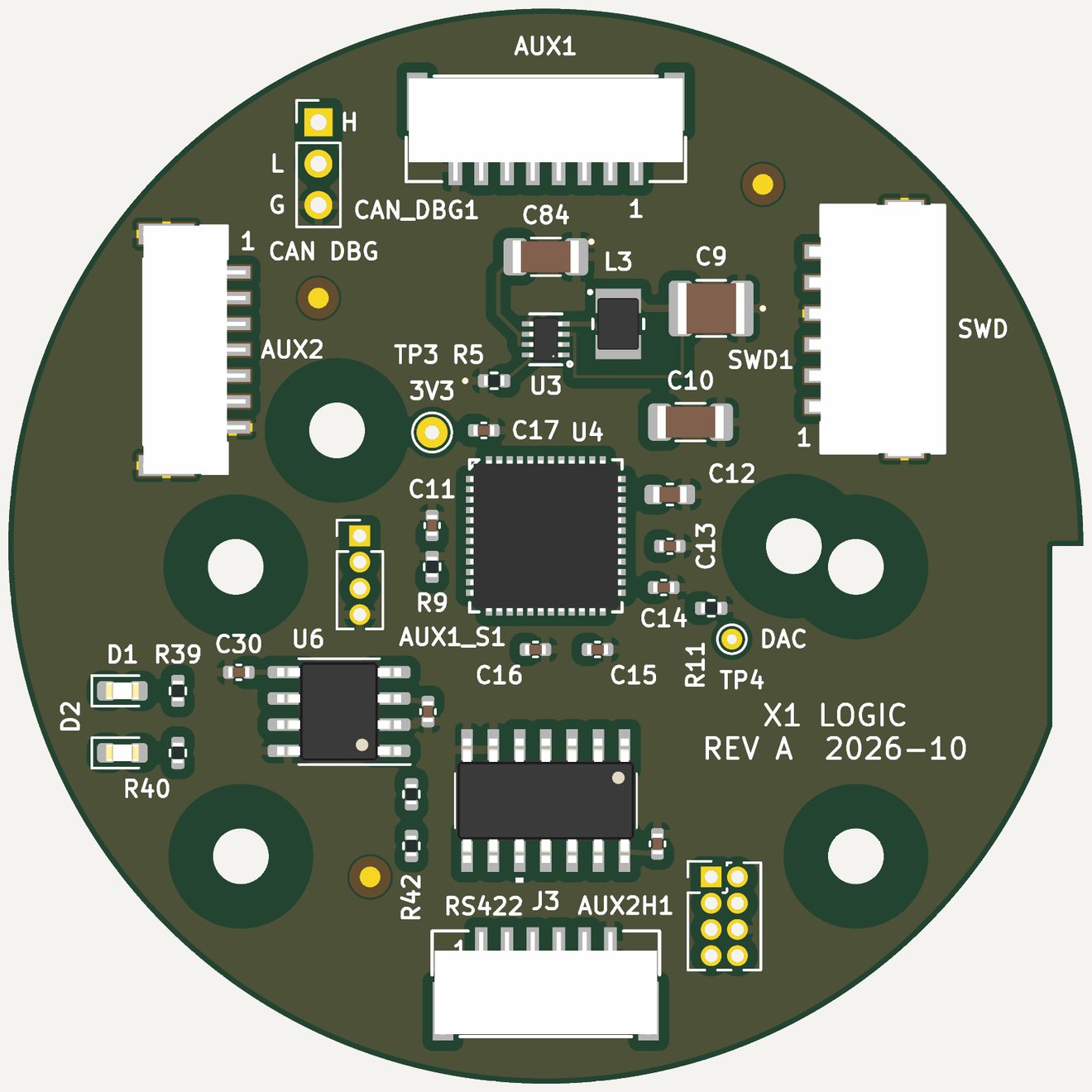
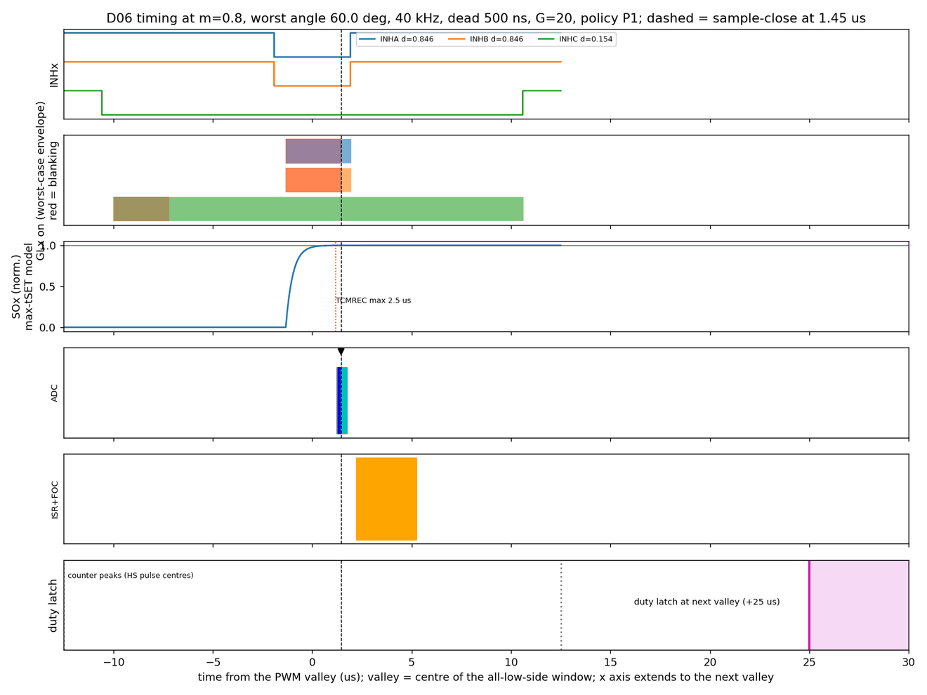
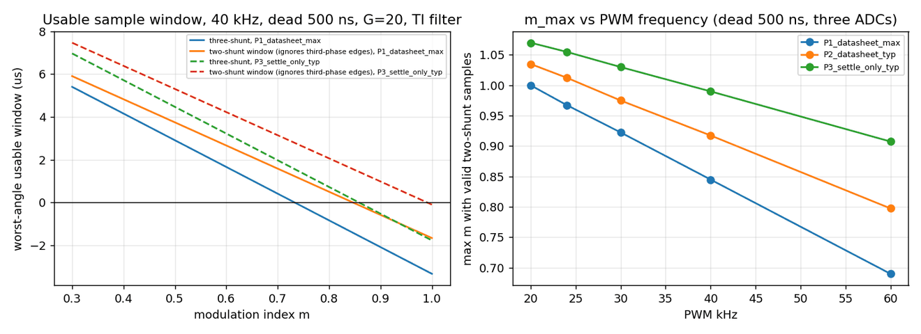
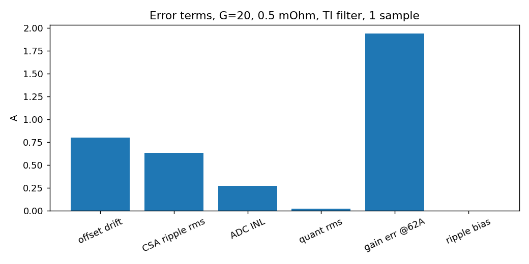
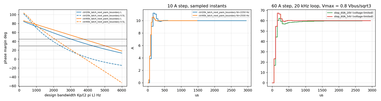
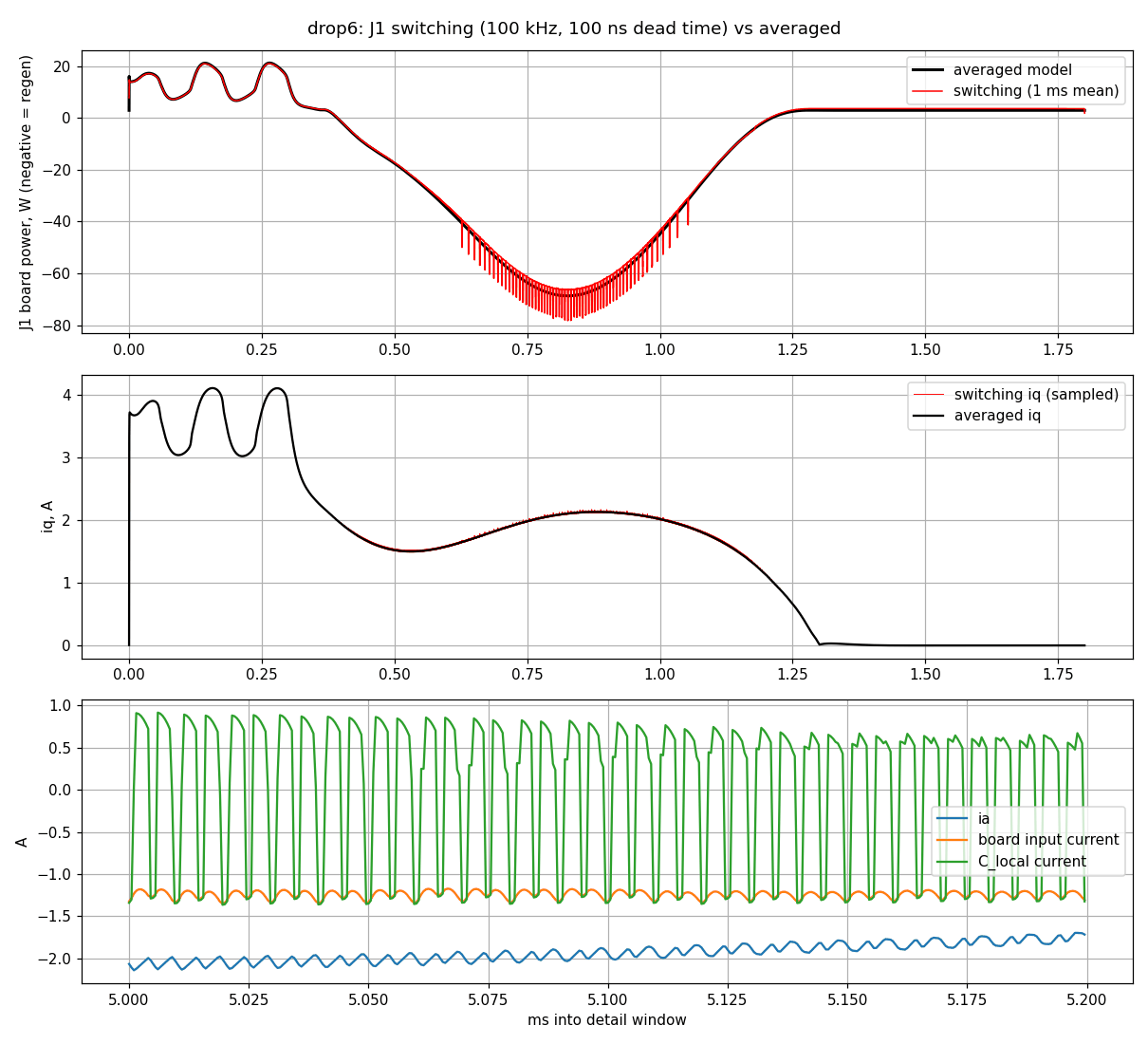
The logic board carries the STM32G474 controller, CAN and RS-422, and stacks on each power-stage board. The current-sense amplifiers are on the power board, but the controller sets when the ADC samples them, so the sense-timing study belongs here. It is a Python timing model at 40 kHz PWM with 500 ns dead time, using the datasheet settling and blanking times.
Power-stage boards (WGG and P96)
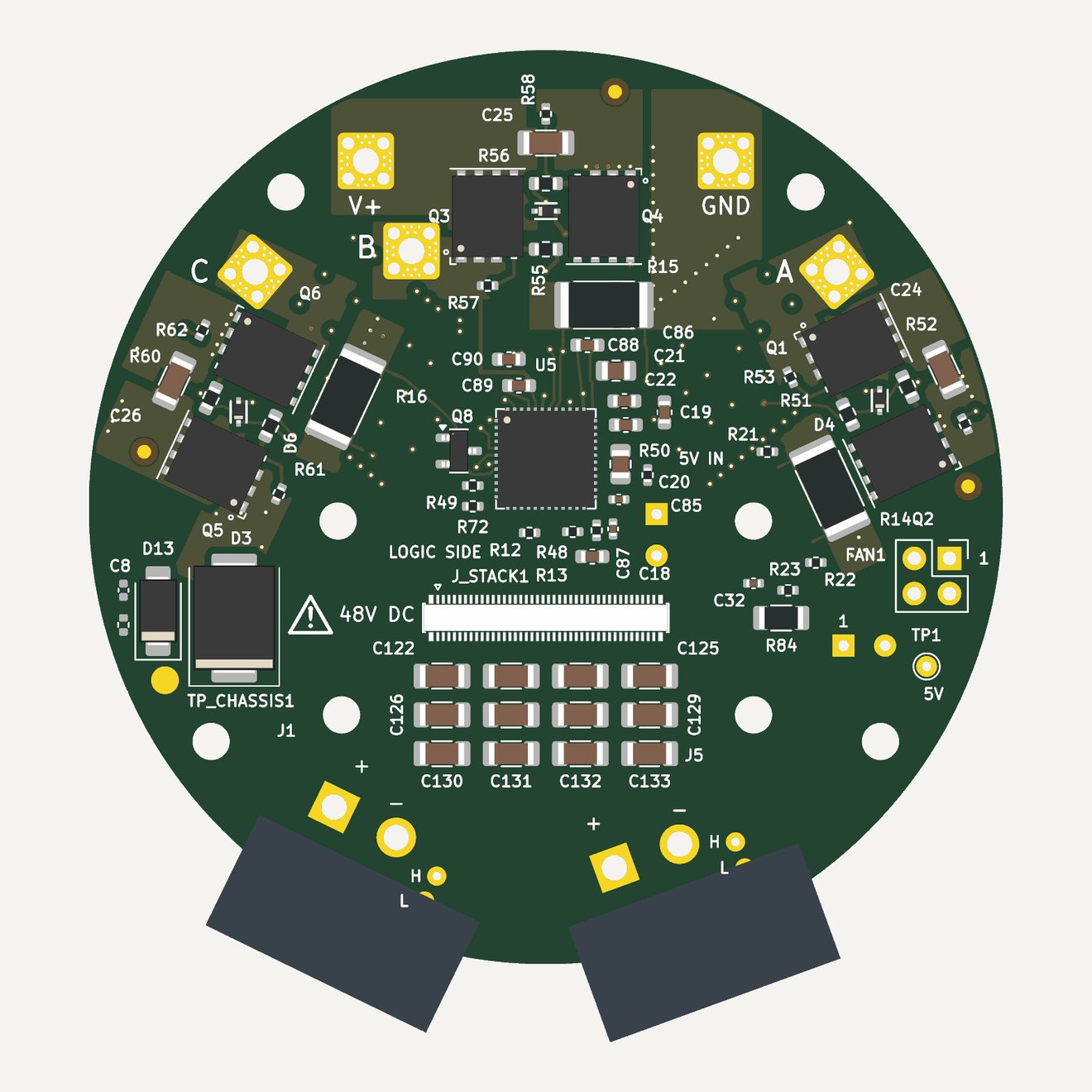
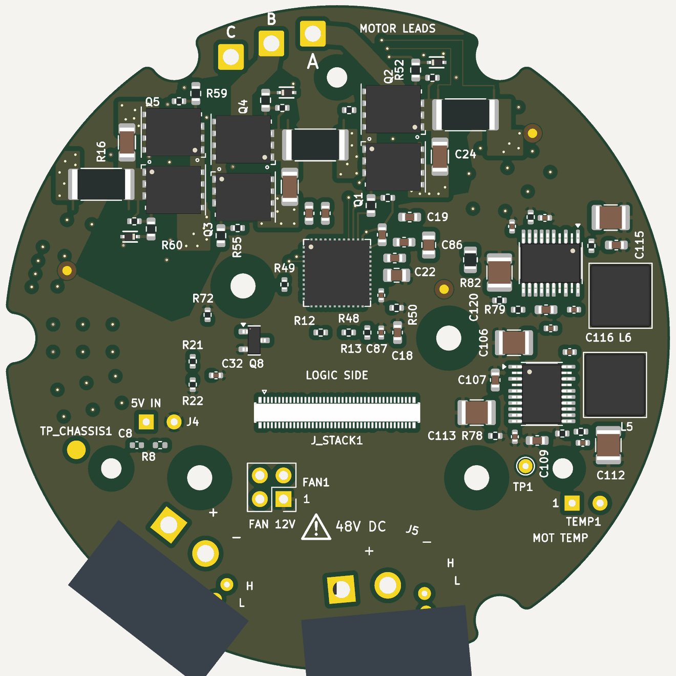
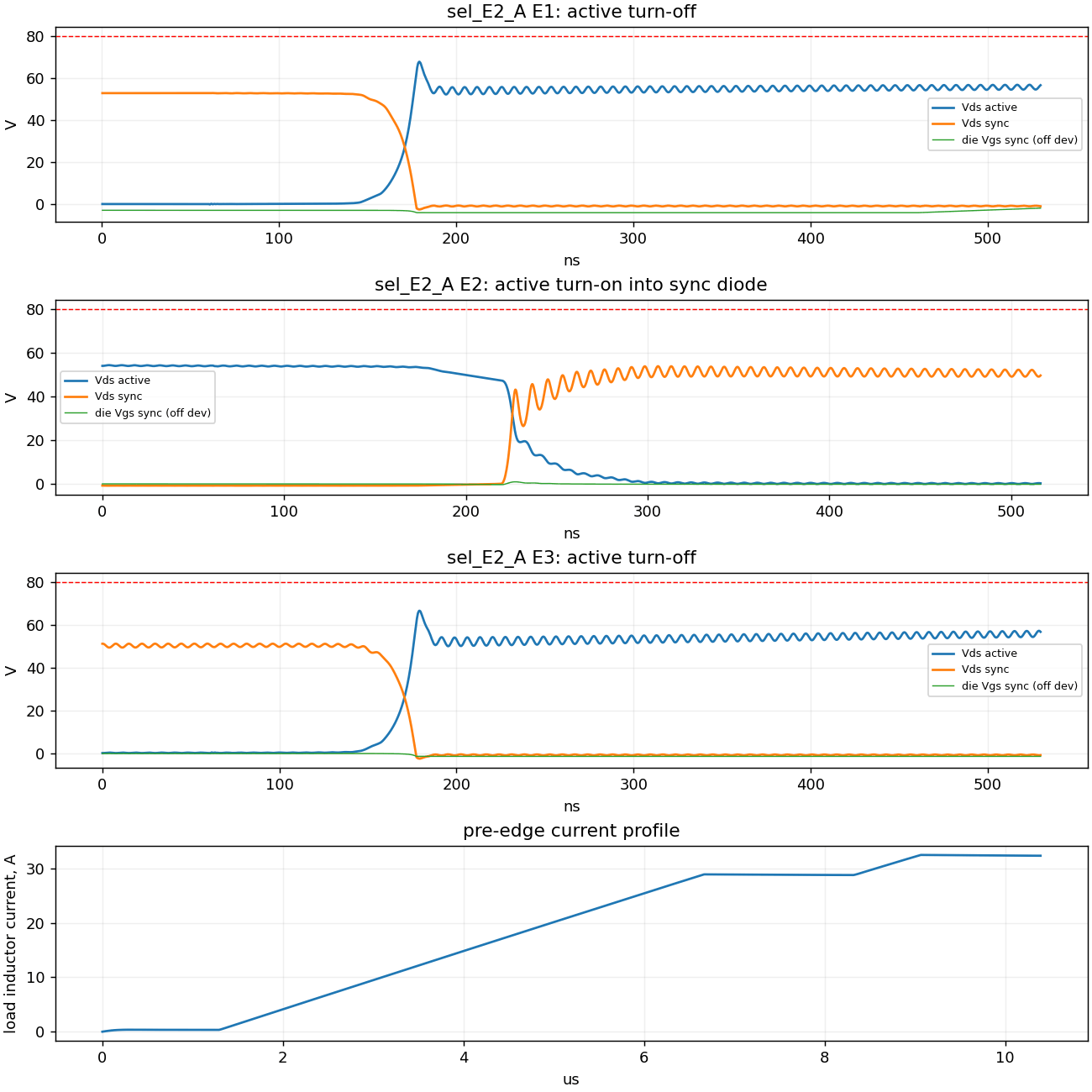
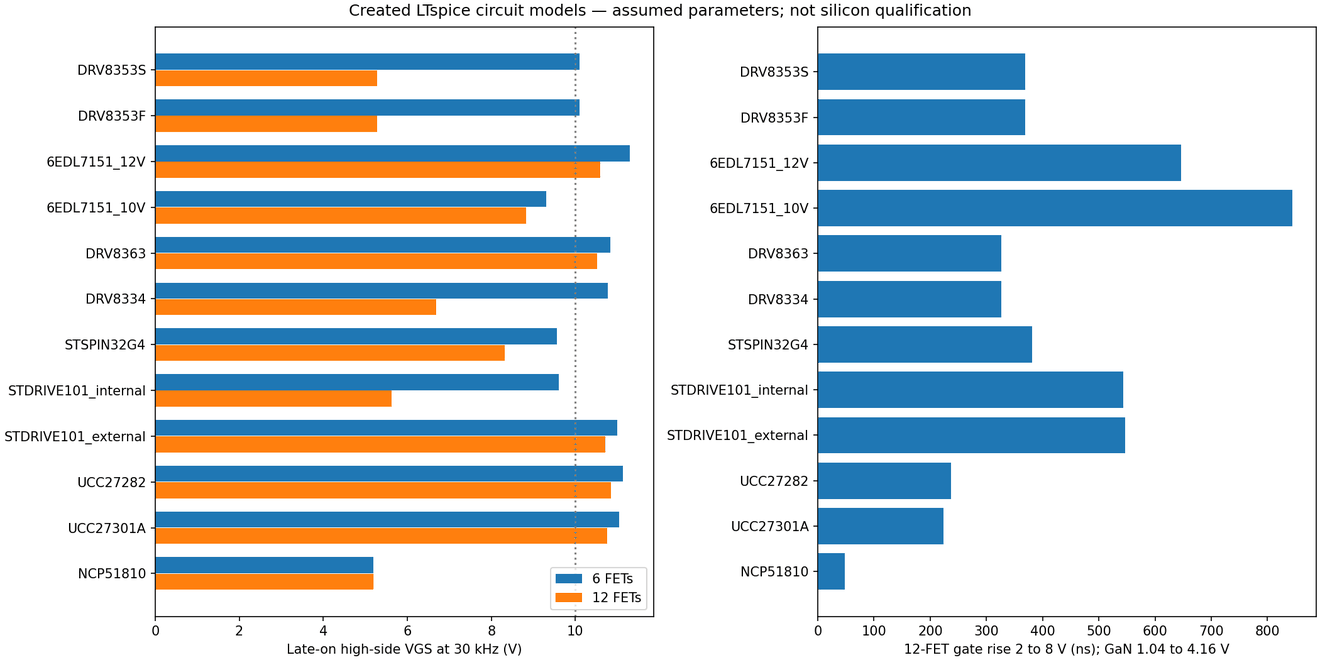
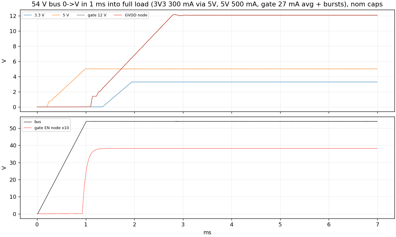
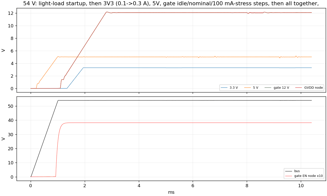
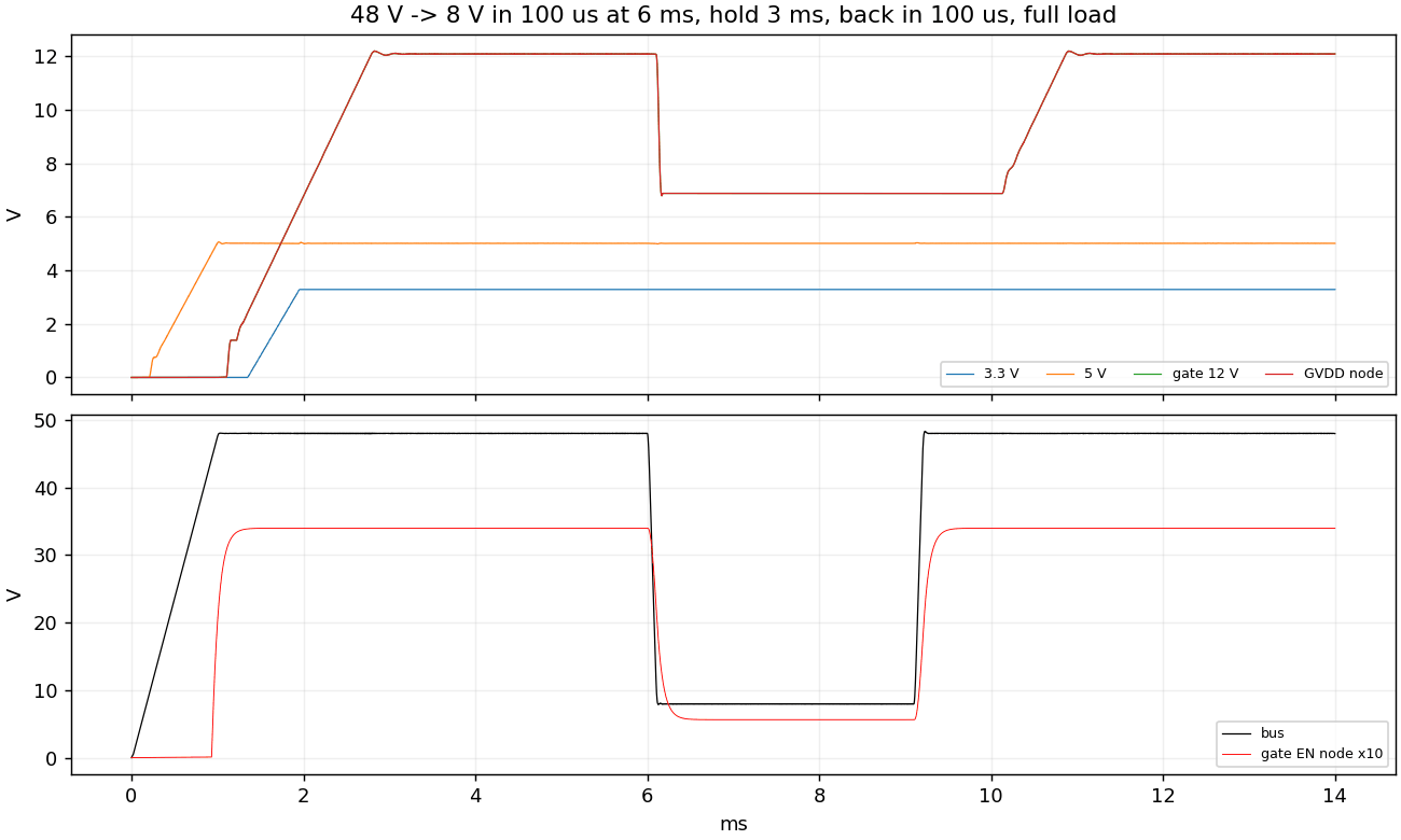
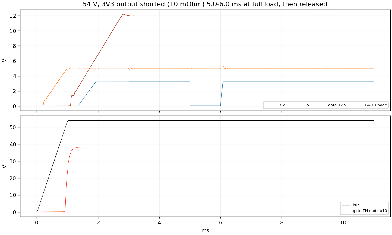
The two power-stage boards share one circuit: a DRV8363 gate driver, six ISC060N10NM6 100 V MOSFETs with shunts, and three LT8631 converters for 3.3 V, 5 V and the 12 V gate supply. Only the outline and placement change for each actuator size. The charts are LTspice runs with vendor MOSFET and LT8631 models. They are screening runs, not qualification.
Support board
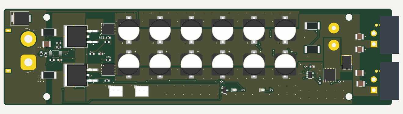
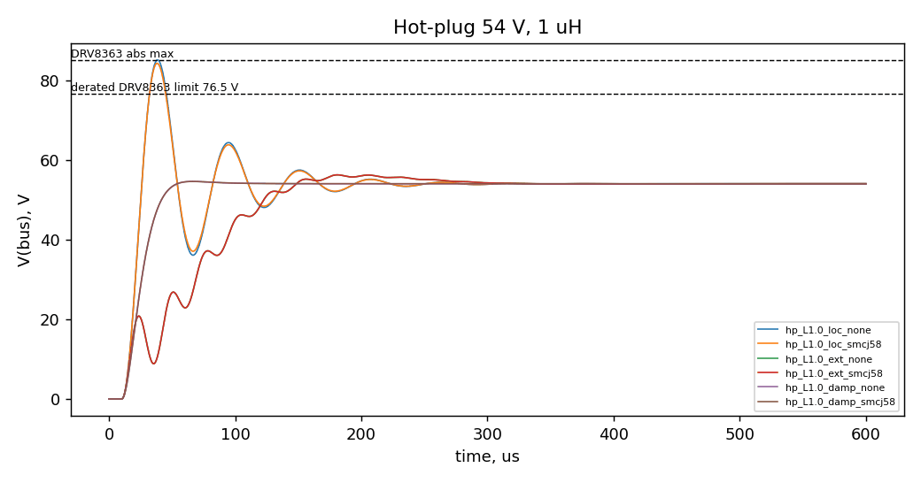
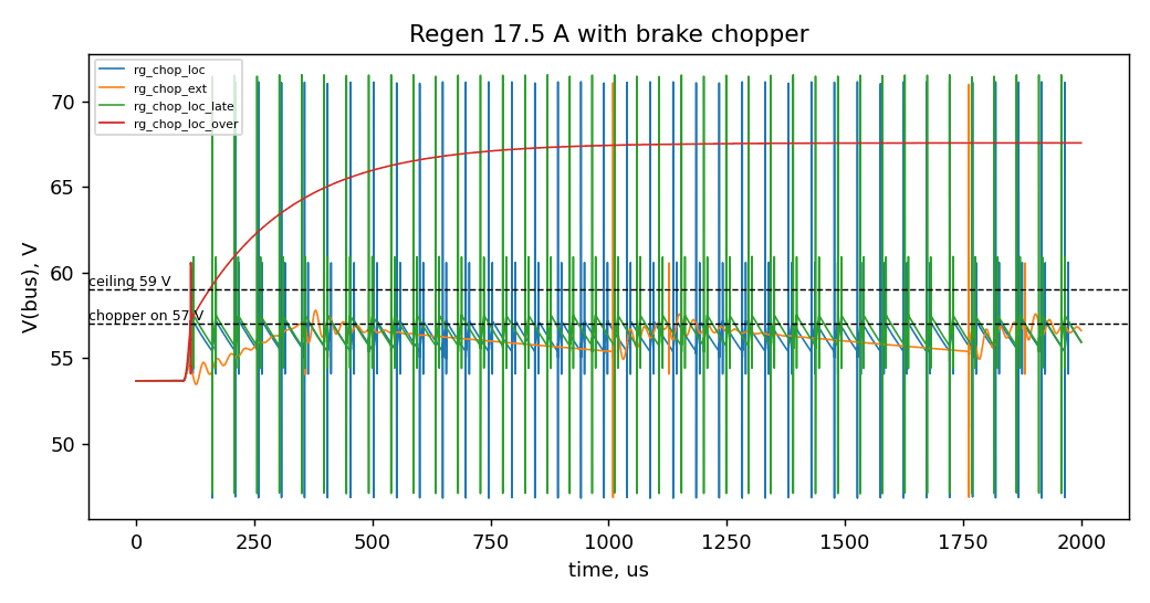
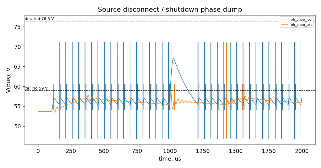
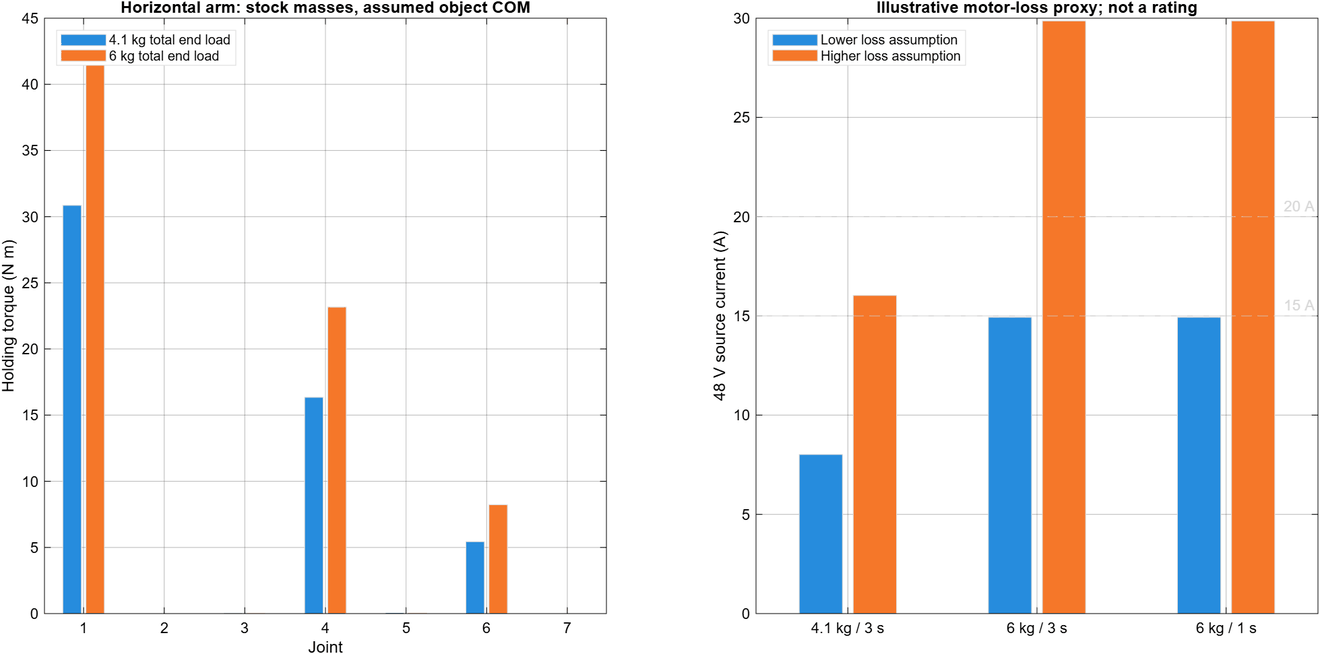
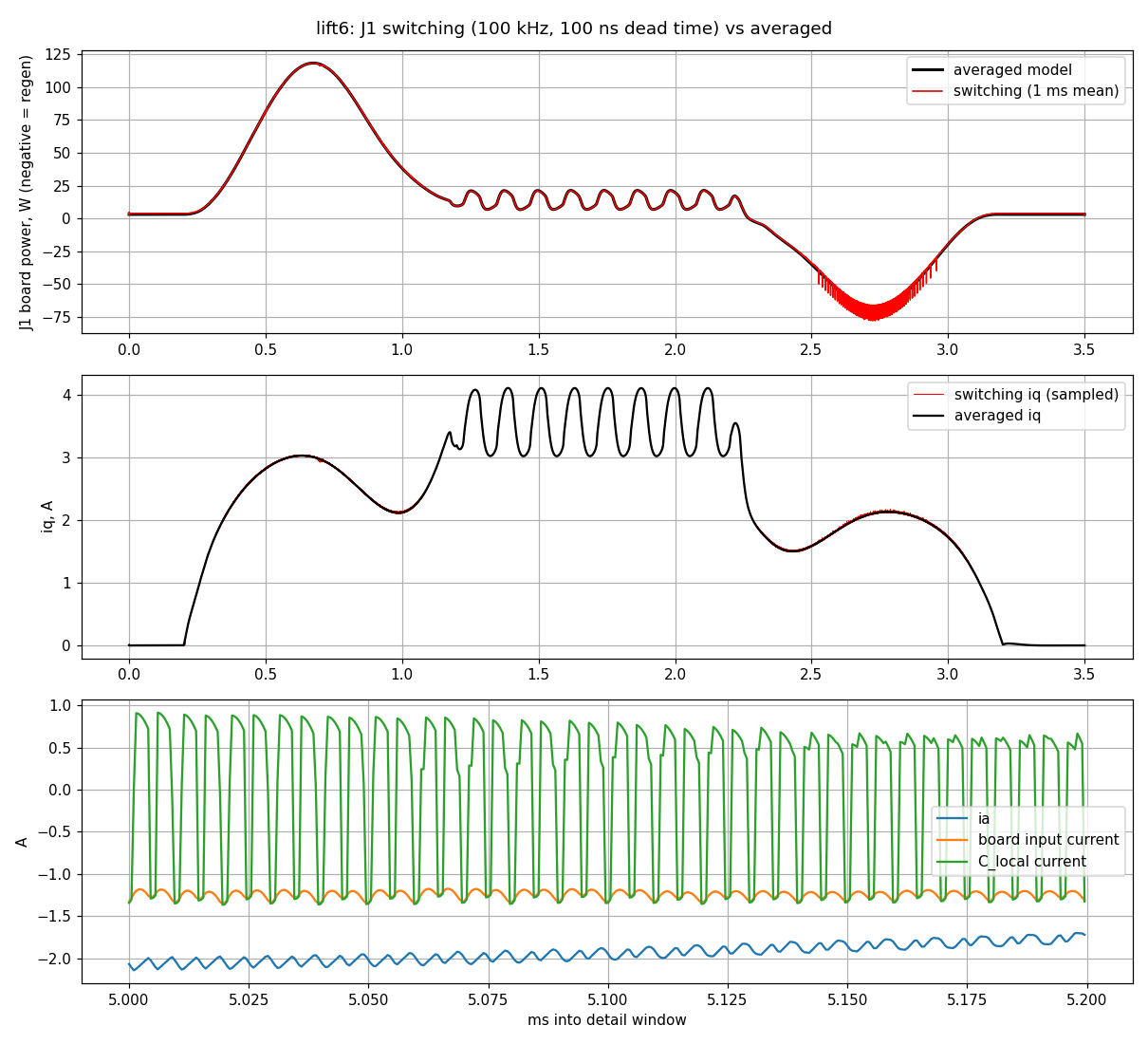
One support board on each arm takes the 48 V supply. It holds the hot-swap and precharge, the bulk capacitor bank, the power and CAN chain ports, and the brake chopper. The bus-protection charts are LTspice runs with a behavioural TVS and comparator. The DRV8363 supply pin on each power board sets the limit: 85 V absolute maximum, derated to 76.5 V. A MATLAB load study of OpenArm 2.0 used 20 A continuous and 40 A peak per arm as provisional design inputs. The board still needs current and thermal testing.
Brake resistor board
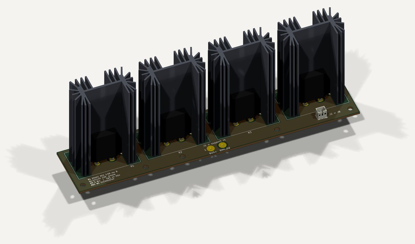
The brake resistor board is the load for the support board chopper. The Simulink model of one arm sizes it: seven actuators, the support board, the daisy chain and the brake. When the arm lowers a 6 kg load, the motors push energy back into the bus. The primary brake holds the bus at 57.2 V. If the aux supply fails, the bus-powered backup brake holds it at 61.2 V. Without a brake the bus reaches 142 V. A hand check against the LTO100 pulse curve gives a margin of about 17 times for pulses of up to 71 J. The 190 × 38 mm Rev B strip puts all four heatsinks in a row. Its cooling and the thermostat interlock still need bench testing.
Stack-connector breakout boards
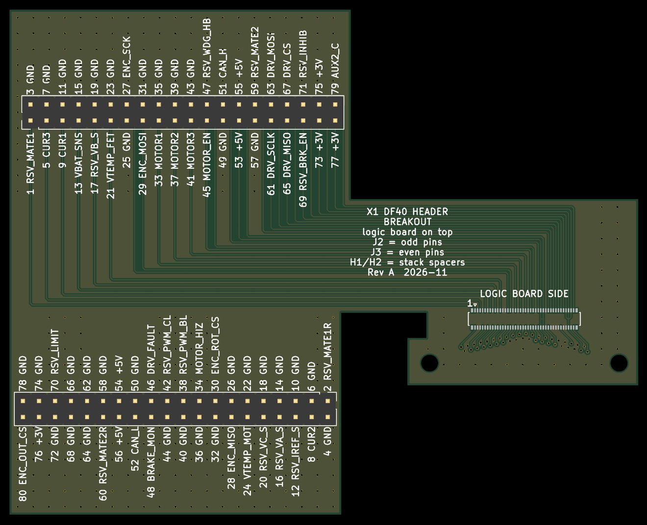
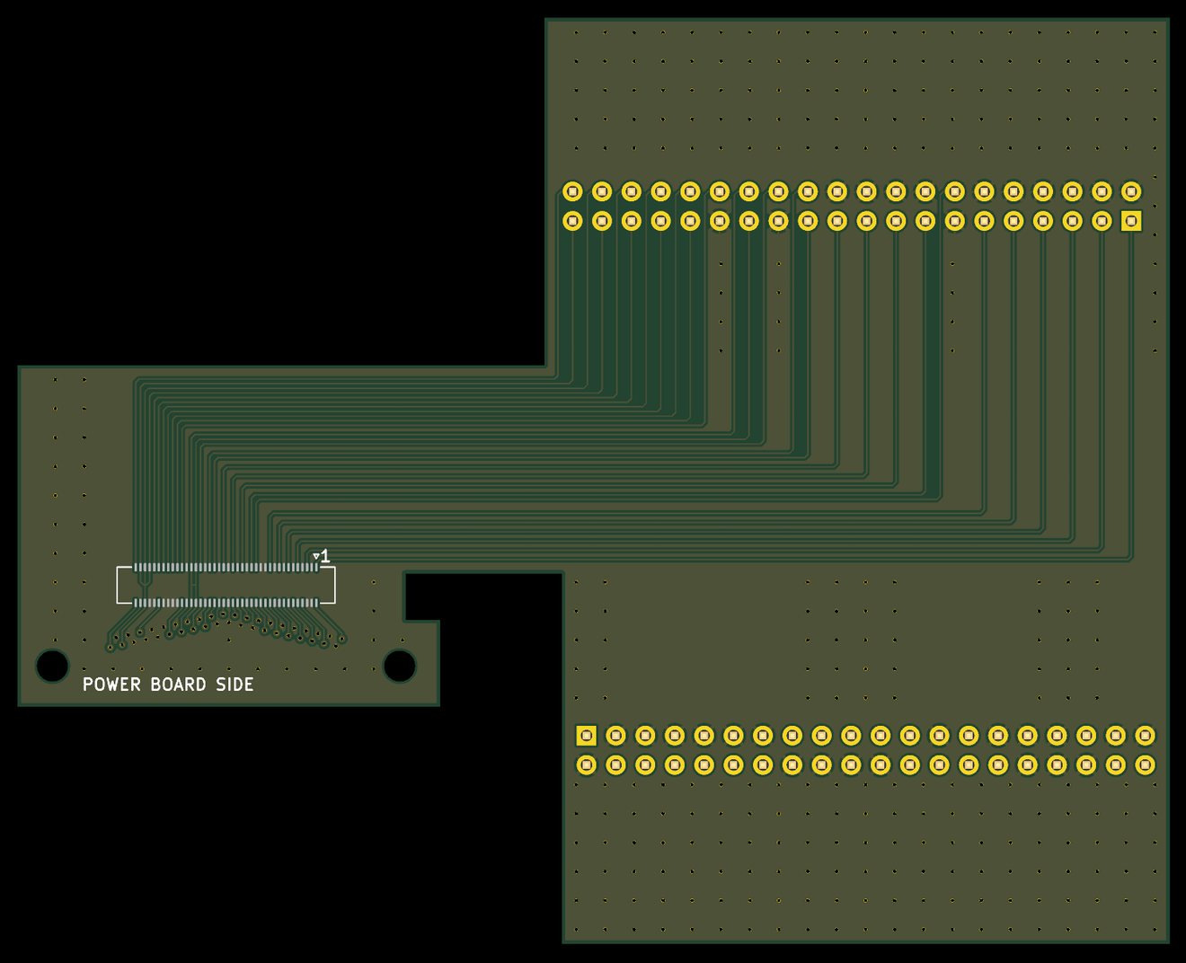
A Hirose DF40 connector joins each logic board to its power-stage board. It has 80 contacts at 0.4 mm pitch, so the signals cannot be probed on the stack. Two breakout boards bring each contact out to a labelled 0.1-inch header pin, for bench tests of one board at a time. The logic board plugs onto the header breakout. The receptacle breakout plugs onto a power-stage board in place of the logic board. No commercial DF40 80-pin breakout was available.
The boards have two layers. A script generates the fan-out, because an autorouter could not escape the 0.4 mm pitch. The headers are outside the edge of the power-stage boards, so no pin is above a power-stage board. Tented vias tie the two ground pours together. The KiCad rules target JLCPCB’s standard two-layer process. Fabricator review, mating checks and electrical tests are still open.
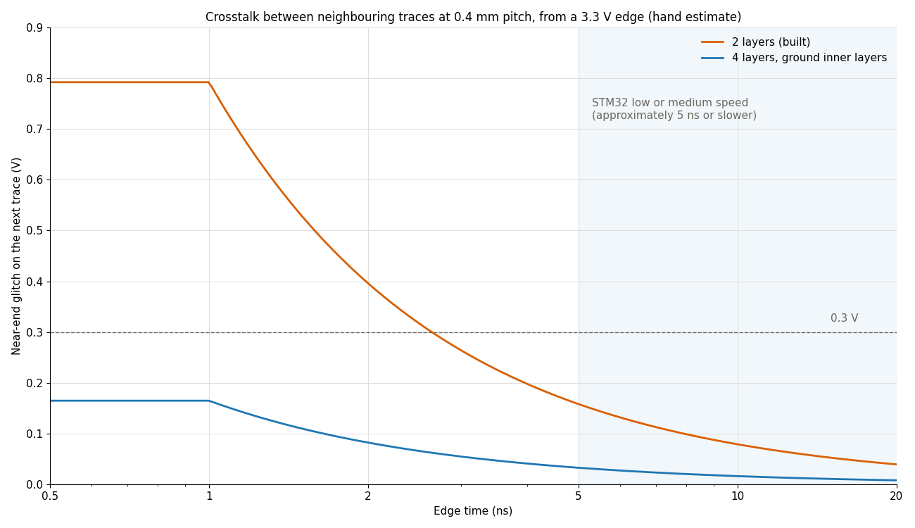
There is no ground plane under the traces, so the crosstalk between neighbouring traces depends on the edge time. The chart is a hand calculation, not a simulation. The estimate assumes slower edges from the microcontroller’s low or medium GPIO speed settings. Measure crosstalk on the assembled boards.
Solved flux overlays for the optimised motors
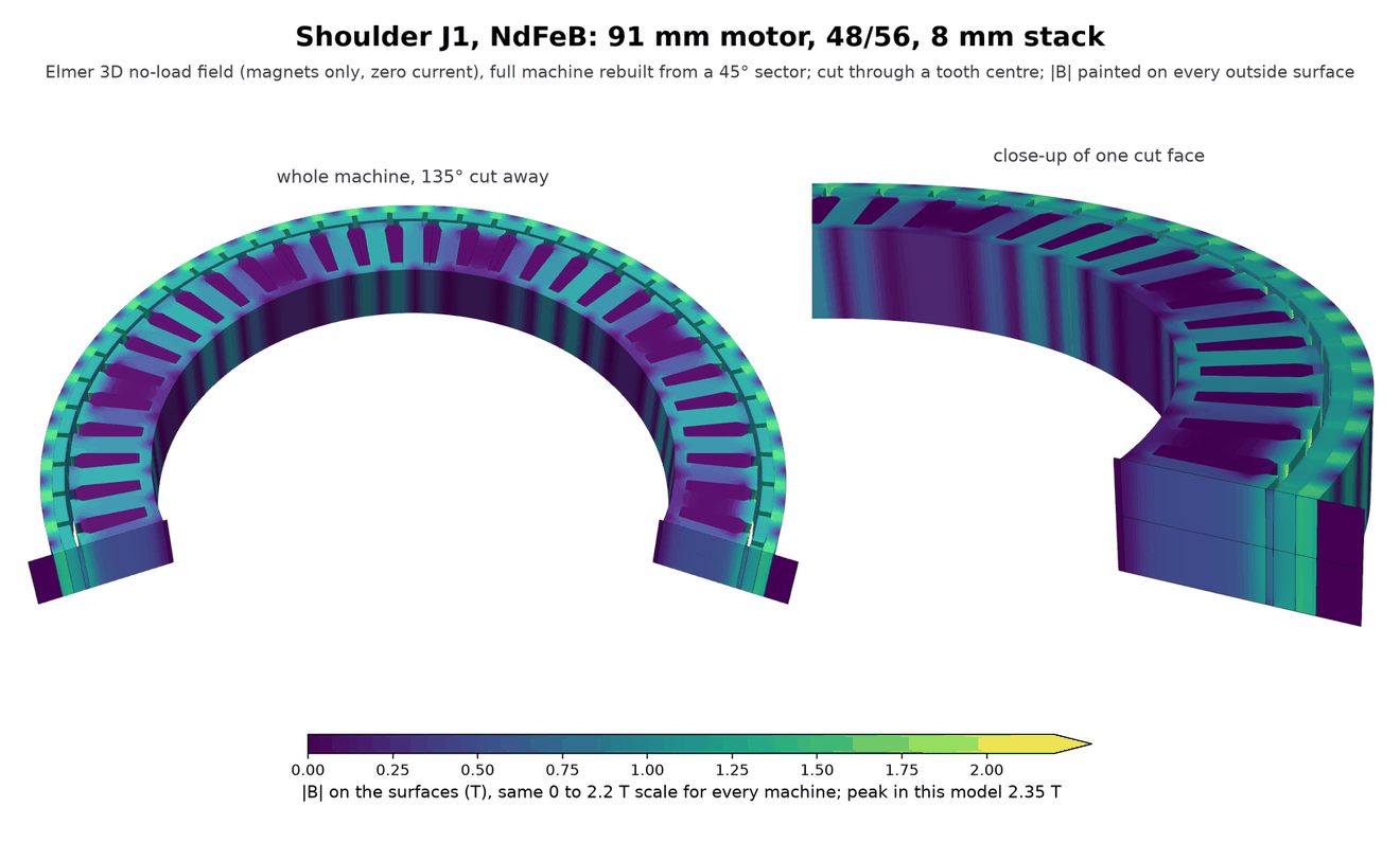
The 3D no-load solves are finished for the shoulder, upper arm, wrist and torso picks, with NdFeB and low-cogging 30-pole ferrite at each joint. The shoulder pair below shows magnetic flux density mapped onto the motor surfaces and cut faces. All eight comparisons, full painted views, field lines and end-leakage checks are on the rotor-study page. These are simulated permanent-magnet fields at zero winding current, not loaded motor or controller-board results.